Bypass process and system for cement kiln

A bypass ventilation and cement kiln technology, which is applied in the field of bypass ventilation system, can solve problems such as the influence of waste heat boiler operation at the kiln tail, the increase of heat consumption and material consumption in cement production and operation costs, and the increase in equipment and civil engineering investment costs, etc.

Inactive Publication Date: 2014-01-01
HUAXIN CEMENT +2
View PDF9 Cites 9 Cited by
  • Summary
  • Abstract
  • Description
  • Claims
  • Application Information

AI Technical Summary

Problems solved by technology

[0004] In addition, the process flow of the existing cement kiln bypass air release device is mainly: the flue gas released from the tail smoke chamber of the cement rotary kiln through the bypass and the cold air blown by the cooling fan are mixed in the mixing chamber and quenched to about 400°C. The flue gas is then cooled to below 250°C by heat exchange through the cooling fan, and finally discharged through the bag filter; long-term practical application has proved that this bypass ventilation process not only increases the investment cost of equipment and civil engineering, but also due to The loss of heat consumption and material consumption in cement production increases the cost of production operation
The other is to pass the flue gas released from the tail smoke chamber of the cement rotary kiln through the bypass through sedimentation and separation, and then input it into the waste heat boiler at the kiln tail for power generation. Its disadvantage is that the flue gas after sedimentation contains a lot of dust, Since the flue gas contains a lot of dust during the heat exchange process of the boiler, it will affect the operation of the waste heat boiler at the kiln tail, and ultimately affect the stable operation of the cement production system

Method used


Image

  • Bypass process and system for cement kiln

Examples


Embodiment Construction

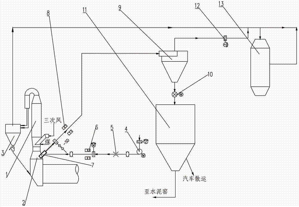
[0017] In order to better understand the present invention, the present invention will be further described below in conjunction with the accompanying drawings and embodiments.

[0018] Such as figure 1 Shown is the flow chart of cement kiln bypass ventilation process and system. The main body of the cement kiln bypass ventilation system is connected with the calciner 1 and the kiln tail smoke chamber 2 at the bottom of the calciner 1 respectively, and the main body of the calciner 1 is connected with the kiln tail smoke chamber 2 at the bottom; The multi-stage cyclone tube 3 of the heater is connected, the kiln tail smoke chamber 2 is provided with a bypass flue gas channel, and the bypass flue gas channel is connected to the cyclone separation device 9 through the mixing chamber 7; the gas outlet of the cyclone separation device 9 is connected to the kiln tail waste heat boiler 13 ; The dust outlet of the cyclone separation device 9 is connected to the bypass ash bin 11 . ...


PUM


Abstract

The invention relates to a bypass process and a bypass system for a cement kiln. After bypass flue gas discharged from a feed-end chamber of the cement kiln passes through a mixing chamber to be subjected to heat exchange cooling, the flue gas passes through a cyclone separation device and over 80 percent of dust enters a bypass ash bin; after gas discharged from the cyclone separation device is mixed with the flue gas separated from the top of the kiln tail of the cement kiln, the mixed gas enters a kiln tail waste heat boiler to carry out waste heat power generation; and the dust which is separated from the cyclone separation device and enters the bypass ash bin is conveyed to a cement grinding mill to carry out cement batching or is loaded in bulk and transported out of a factory by a vehicle to be processed. The quantities of chlorine in ash and chlorine in RDF (Refuse Derived Fuel), which are taken into the cement kiln, can be reduced; the feed-end chamber is prevented from being crusted and blocked; and a bypass is sufficiently utilized to extract flue gas waste heat; and meanwhile, the bypass system is more flexible for model selection and has strong adaptability and cost is greatly reduced.

Description

technical field [0001] The invention relates to the technical field of domestic waste treatment, in particular to a bypass ventilation system and process for co-processing urban domestic waste by using a cement kiln. Background technique [0002] Co-processing of municipal solid waste in the cement industry generally involves drying and dehydrating primary solid waste into RDF, sending it to a decomposition furnace for combustion, or directly sending domestic waste to a gasifier for gasification and then entering a decomposition furnace for incineration. [0003] In the traditional production process, the volatilization of harmful elements causes skinning and blockage, which affects the normal operation of the cement kiln system. Generally, a bypass ventilation system is required to release the flue gas from the kiln tail outside the kiln. The co-processing of MSW in cement kilns has inherent advantages. The disposal process does not generate dioxins and garbage fly ash; ho...

Claims


Application Information

Patent Timeline
Patent Type & Authority Applications(China)
IPC IPC(8): F27D17/00
CPCY02P10/25
Inventor 李叶青王加军胡贞武陈智魏茂
Owner HUAXIN CEMENT
Why Eureka
Try Eureka