

Vehicle temperature adjusting apparatus, and vehicle-mounted thermal system
A temperature control device and temperature control technology, applied in the field of vehicle thermal systems, can solve the problems of undescribed heat storage, undisclosed, complicated structure, etc.
- Summary
- Abstract
- Description
- Claims
- Application Information
AI Technical Summary
Problems solved by technology
Method used
Image

Examples
no. 1 example
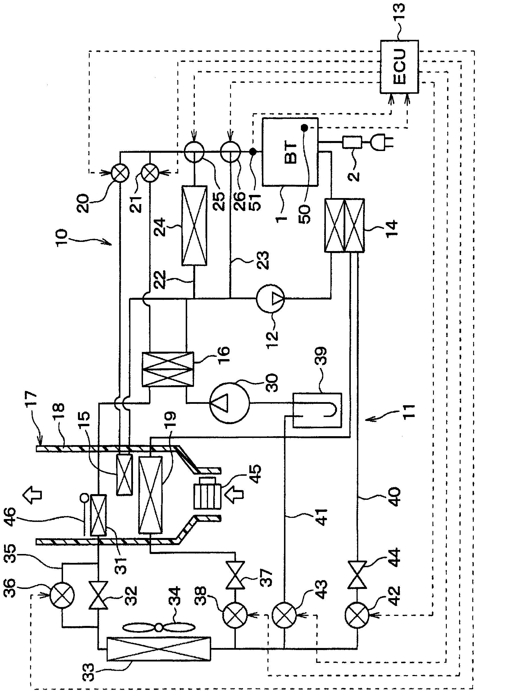
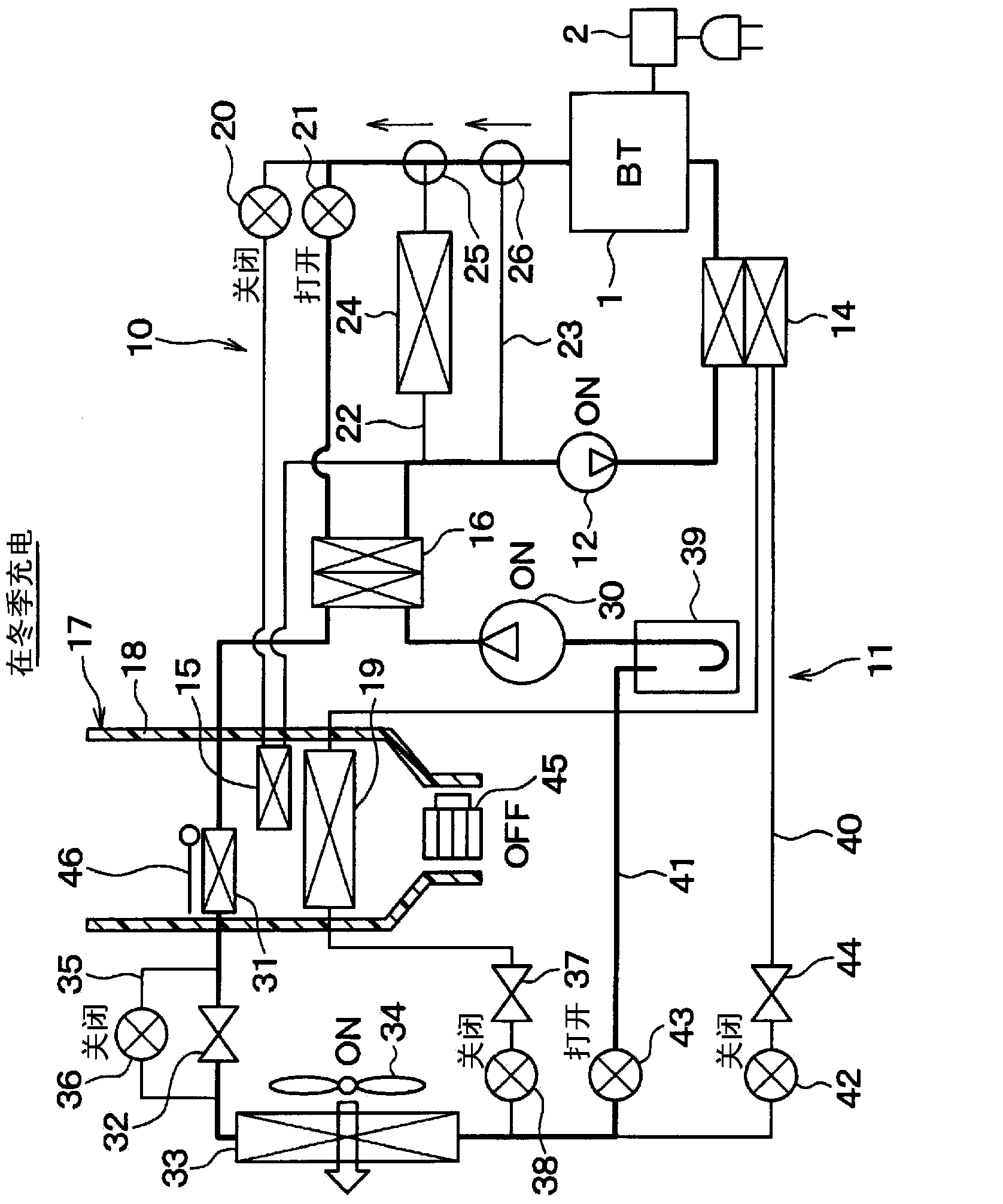
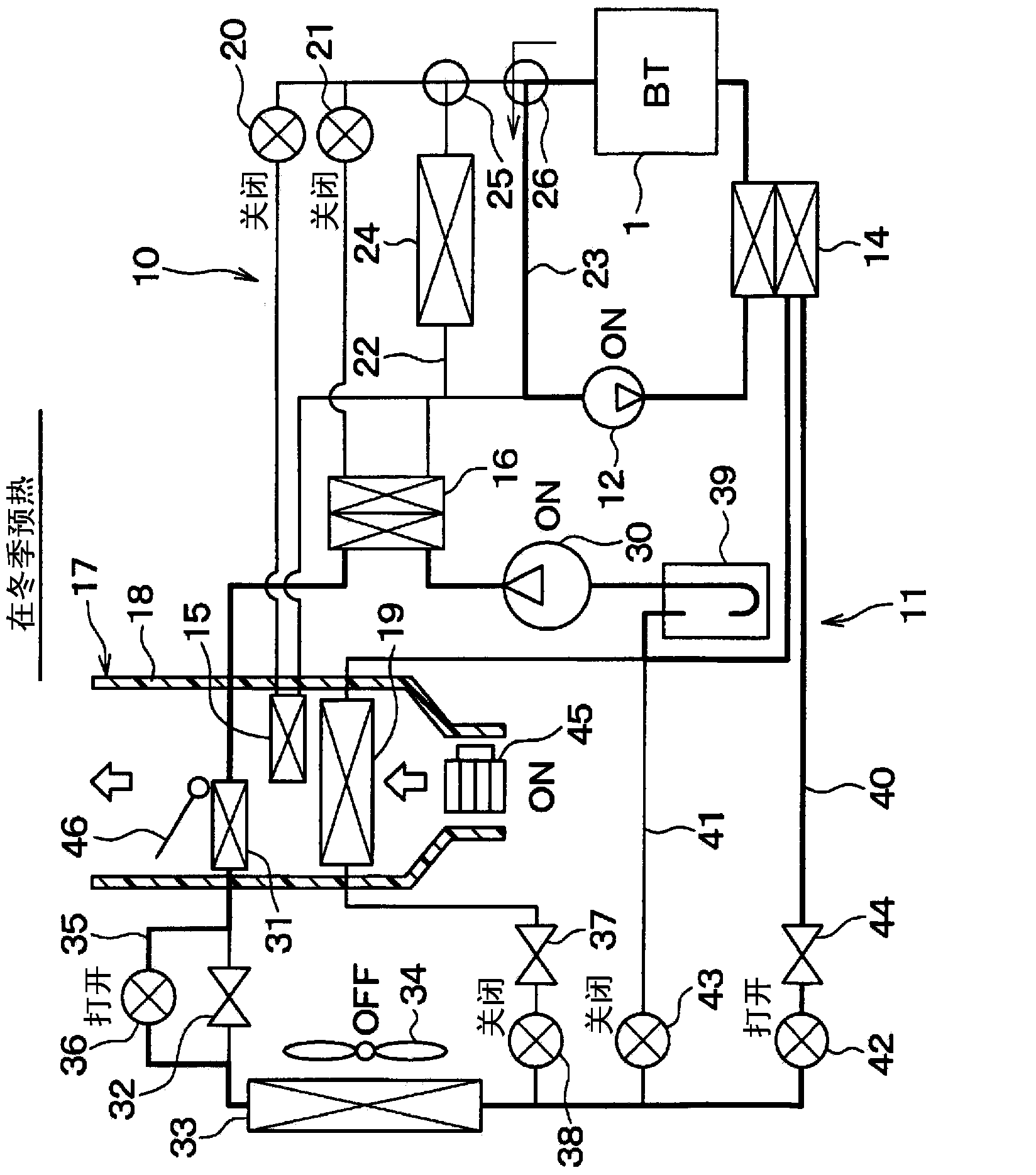
[0056] A first embodiment is described below. figure 1 is an overall schematic diagram of the temperature control device for a vehicle in this embodiment. The temperature control apparatus for a vehicle in this embodiment functions as a vehicle air conditioner, and uses the air in the vehicle compartment as a temperature control object.
[0057] Specifically, the temperature control apparatus for a vehicle in this embodiment is used as a vehicle air conditioner for a plug-in hybrid vehicle (ie, an electric vehicle). Among hybrid vehicles that obtain driving force for vehicle travel from an internal combustion engine and an electric motor for vehicle travel, plug-in hybrid vehicles are those that can be supplied from an external power source (ie, a commercial power source) every time the vehicle is stopped. A vehicle that charges a secondary battery (ie, a high-voltage battery) with electric power.
[0058] In addition, the temperature control apparatus for vehicles in this e...
no. 2 example
[0162] While the first embodiment described above was presented as an exemplary structure in which the refrigeration cycle 11 is used as a heat pump cycle usable for both heating operation and cooling operation, the refrigeration cycle 11 in the second embodiment of the present disclosure is used as a heat pump cycle for the vehicle compartment. Cooling cycles for cooling operations such as Figure 10 (a), (b), (c) shown.
[0163] More specifically, in the second embodiment, the internal condenser 31, the air volume adjustment door 46, the first expansion valve 32, the expansion valve bypass passage 35, the first electromagnetic refrigerant described in the above-mentioned first embodiment The valve 36 , the second bypass refrigerant passage 41 , and the fourth electromagnetic refrigerant valve 43 are omitted below.
[0164] exist Figure 10 In the example of (a), the second coolant-refrigerant heat exchanger 16 is provided between the external heat exchanger 33 and the seco...
no. 3 example
[0167] The third embodiment further adds an internal heat exchanger 47 to the example of the second embodiment described above, as Figure 11 (a), (b), (c) shown.
[0168] The inner heat exchanger 47 is used for heat exchange between the high-pressure refrigerant flowing out of the outer heat exchanger 33 and the low-pressure refrigerant flowing out of one of the first coolant-refrigerant heat exchanger 14 and the inner evaporator 19 . Therefore, the inner heat exchanger 47 cools the high-pressure refrigerant flowing out from the outer heat exchanger 33 for realizing the enthalpy reduction function of reducing the heat enthalpy of the refrigerant flowing into the inner evaporator 19 and for realizing the A liquid compression suppression function that prevents liquid compression in the compressor 30 due to the enthalpy of the suction refrigerant to be sucked into the compressor 30 rising to such a level that the suction refrigerant of the compressor 30 will be in the gas phase....
PUM
 Abstract
Description
Claims
Application Information