Combination welding pipe and manufacturing method and application thereof

A manufacturing method and combined pipe technology, applied in applications, manufacturing tools, welding equipment, etc., can solve problems such as overburning of copper pipes, variability of pipes, general strength of welds, etc., achieve smooth and bright welding joints, and improve welding quality , cost reduction effect

Active Publication Date: 2014-01-08
佛山晓世科技服务有限公司
View PDF7 Cites 8 Cited by
  • Summary
  • Abstract
  • Description
  • Claims
  • Application Information

AI Technical Summary

Problems solved by technology

The surface of the welded pipe fittings looks beautiful, but the strength of the weld is average
If iron pipes are used for welding at a similar temperature, the copper pipes will be over-burned and dirty, and the copper and iron pipes cannot be welded.
[0006] Moreover, on the one hand, during flash welding, the thermal conductivity of copper and iron has a relationship of about 5 times, while during flash welding, due to the separation and approach of copper and iron pipes, the temperature at the end of the copper pipe fluctuates greatly. It is not easy to form a stable liquid metal layer on the end face of the copper pipe section, and it is also difficult to maintain a stable flashing process; on the other hand, when the end face of the copper pipe section reaches its melting point, it softens rapidly and in large sections, and it is necessary to increase the upsetting process. speed
Such a result will produce two disadvantages, one is the variability of the pipeline, and the other is the need to clamp the copper and iron pipes to implement the upsetting force. The clamping force is easy to pinch the surface of the copper and iron pipes, making it necessary to correct the surface after welding. Handling of pinch marks

Method used


Image

  • Combination welding pipe and manufacturing method and application thereof
  • Combination welding pipe and manufacturing method and application thereof
  • Combination welding pipe and manufacturing method and application thereof

Examples


Embodiment 1

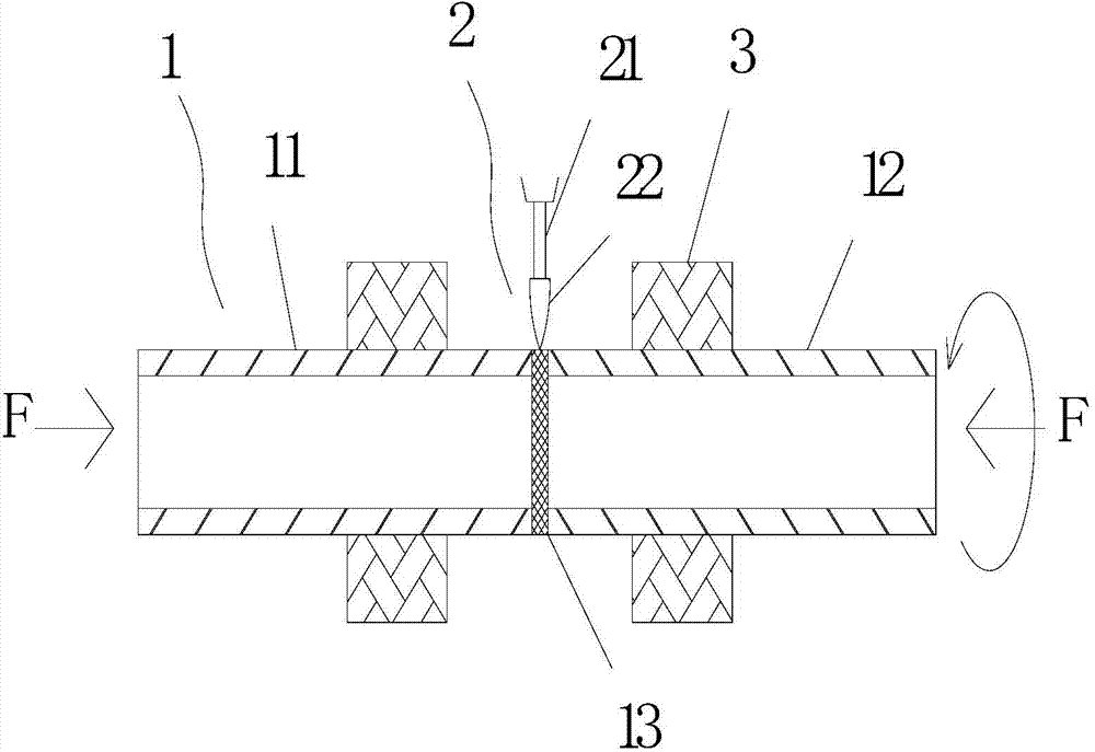
[0034] In this embodiment, an argon arc welding machine 2 is used to prepare the compressor exhaust pipe 1 . Such as figure 1 As shown, first, the copper pipe section 11 and the iron pipe section 12 with the same inner diameter and outer diameter are fixedly installed on the fixture 3 according to the butt position relationship, and the copper pipe section 11 and the iron pipe section 12 are in contact with each other before welding. . When the copper pipe section 11 is in contact with the iron pipe section 12 port, the other end of the copper pipe section 11 and the other end of the iron pipe section 12 respectively apply a force F in the opposite direction, so that the copper pipe section 11 and the iron pipe section 12 are connected at the interface. Contact is maintained throughout the soldering process. Then determine the relative position of the docking port 13 and the welding torch nozzle 21. The heating equipment adopted in this embodiment is a single welding torch, ...

Embodiment 2

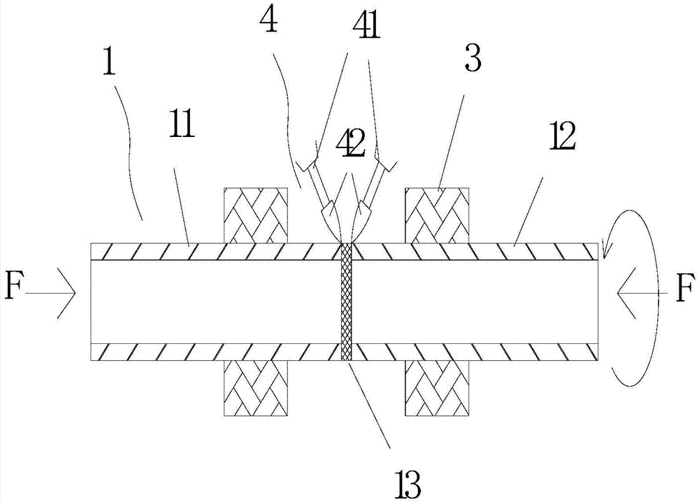
[0036] In this embodiment, the compressor exhaust pipe 1 was prepared using an argon arc welding machine 4, such as figure 2 As shown, firstly, the copper pipe section 11 and the iron pipe section 12 are fixedly installed on the fixture 3 according to the positional relationship of butt joint. When the copper pipe section 11 is in contact with the iron pipe section 12 port, the other end of the copper pipe section 11 and the other end of the iron pipe section 12 respectively apply a force F in the opposite direction, so that the copper pipe section 11 and the iron pipe section 12 are connected at the interface. Contact is maintained throughout the soldering process. Then determine the relative position of the docking port 13 and the welding torch nozzle 41, the heating equipment adopted in the present embodiment is a double welding torch, the output heat of the two welding torches is controlled independently respectively, and a welding torch nozzle 41 corresponding to the hea...

Embodiment 3

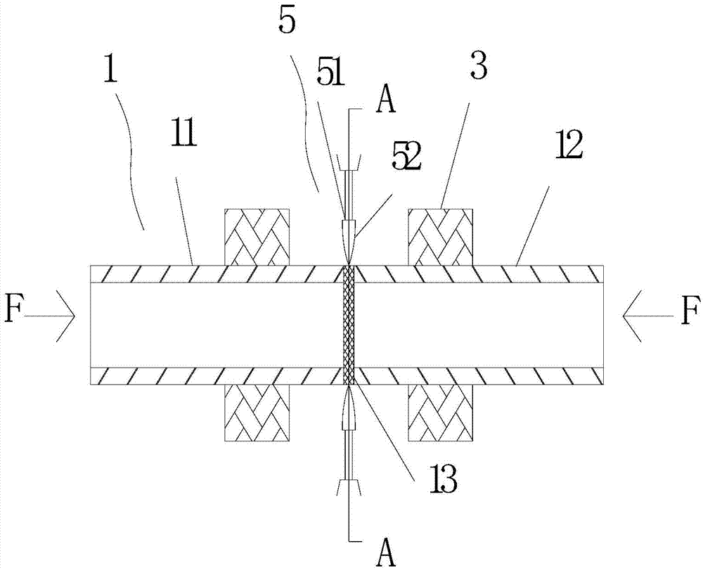
[0038] In this embodiment, an argon arc welding machine 5 is used to prepare the compressor exhaust pipe 1 . Such as Figure 3A As shown, firstly, the copper pipe section 11 and the iron pipe section 12 are fixedly installed on the fixture 3 according to the butt position relationship, and the butt joint 13 does not need solder. Before welding, the butt joints of the copper pipe section 11 and the iron pipe section 12 may contact first, or leave a gap less than 0.5mm.

[0039] The heating equipment adopted in this embodiment is a single annular multi-welding torch, such as Figure 3B As shown, more than 3 welding torches (4 in this embodiment) are evenly distributed around the circumference to form a circular ring. The distribution angles of the welding torches should be distributed reasonably. It is best to let the metal area melted by each welding torch overlap with the metal area melted by the adjacent welding torch. Then the entire welding circumferential surface can be ...


PUM

PropertyMeasurementUnit
melting pointaaaaaaaaaa

Abstract

The invention relates to a combination welding pipe and a manufacturing method and an application thereof. The combination welding pipe comprises pipe sections made of two different kinds of metal materials, higher heat is distributed to a high-melting metal pipe and lower heat is distributed to low-melting metal according to a heat distribution relation through a welding method of a self-melting annular weld bead of argon arc welding or plasma welding or high frequency welding or laser welding or submerged-arc welding or carbon-dioxide arc welding in pipe sections made of different metal materials, and thus synchronous self-melting and butt welding are carried out on butt joint openings of pipe sections of dissimilar materials. The welding process with controllable heat distribution is adopted to weld, the heat is controlled to be properly distributed according to melting points of metal of pipe sections in welding, the butt joint openings of adjacent pipe sections simultaneously or almost reach the melting temperature of metal of the adjacent pipe sections at the same time respectively in welding, thus good fusing is achieved, welding quality is improved, welding openings are smooth and bright, meanwhile pollution is reduced, and cost of welding flux is reduced. The combination welding pipe can be applied to the field of compressors or air-conditioners or the like.

Description

technical field [0001] The invention relates to the field of pipe materials, in particular to a welded composite pipe and its manufacturing method and application. Background technique [0002] In products in various fields, it is often necessary to use connecting pipes, and the materials of the parts connected at both ends of the connecting pipes are usually different. Taking the exhaust pipe and suction pipe of the compressor in the current prior art as an example, most of them are made of copper, one end is welded with other copper pipes, and the other end is brazed with the iron of the compressor by silver solder flame. Cover or iron shell connection. When flame brazing is used, the copper tube is generally embedded in the iron upper cover or iron shell, and the solder is heated and melted by the flame to fill the gap between the copper tube and the iron material, so that the copper tube and the iron tube can be filled in Solder in the gap joins the three together. Wh...

Claims


Application Information

Patent Timeline
Patent Type & Authority Applications(China)
IPC IPC(8): B23K31/02
CPCB23K31/027B23K2101/06
Inventor 孙建康
Owner 佛山晓世科技服务有限公司
Why Eureka
Try Eureka