Fiber bragg grating sensing system based on narrow-band scanning light source and operation method

A fiber grating and sensing system technology, applied in the direction of using optical devices, thermometers with physical/chemical changes, measuring devices, etc., can solve the problems of poor signal-to-noise ratio of sensing signals, low utilization of light sources, and problems that can be demodulated Problems such as the number of sensors and demodulation accuracy can achieve the effect of improving demodulation speed, improving scanning speed, and high signal-to-noise ratio

Active Publication Date: 2014-01-15
NO 34 RES INST OF CHINA ELECTRONICS TECH GRP
View PDF4 Cites 23 Cited by
  • Summary
  • Abstract
  • Description
  • Claims
  • Application Information

AI Technical Summary

Problems solved by technology

[0003] Since only a small part of the broadband light source is used at each moment in the existing fiber grating sensing system, the utilization rate of the light source is low, and the signal-to-noise ratio of the sensing signal is poor.
And because the backen...

Method used


Image

  • Fiber bragg grating sensing system based on narrow-band scanning light source and operation method
  • Fiber bragg grating sensing system based on narrow-band scanning light source and operation method

Examples


Embodiment 1

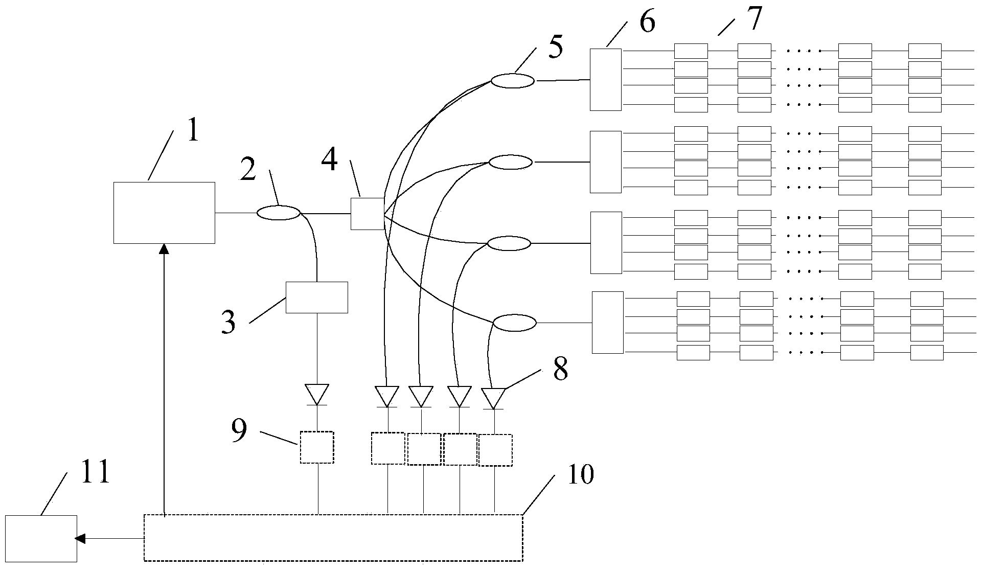
[0028] Embodiment 1 of the fiber grating sensing system based on narrowband scanning light source figure 1As shown, it includes tunable laser 1, 1X2 coupler 2, 1×4 coupler 4, circulator 5, photodetector 8 and 16 sensor channels 7. The tunable laser 1 in this example is a tunable fiber grating-based For the laser, the volume grating-based tunable laser is the same as in this case. The wavelength variation range of the narrow-band light wave whose wavelength is periodically changed by the tunable laser 1 covers the wavelength variation range of each fiber grating sensor in the system. The 1×2 coupler 2 splitting ratio of the example is 90 / 10, 90% of the laser beam is connected to the 1×4 coupler 4, and 10% of the laser beam is connected to the etalon 3. The 2 split from the 1×2 coupler 2 One of the laser channels is connected to a 1×4 coupler 4 to be divided into four sensor channels 7, and the other channel is connected to an etalon 3 as a calibration channel, and the etalon 3...

Embodiment 2

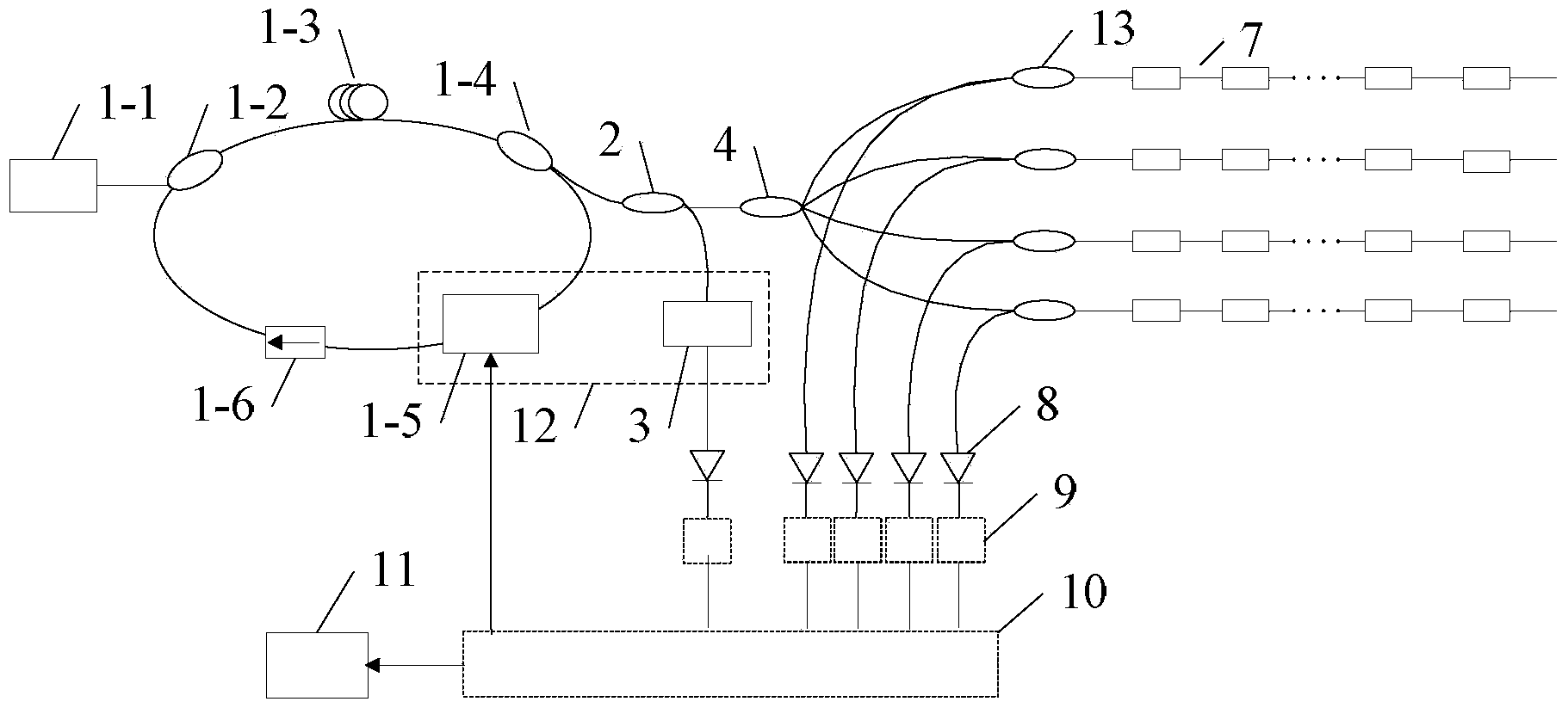
[0032] Embodiment 2 of the fiber grating sensing system based on narrowband scanning light source figure 2 As shown, its basic structure is similar to that of Embodiment 1, and its 4 circulators are replaced by 4 identical 2×1 couplers 13, and the etalon 3 of this example is F-P (Fabry-Perot Fabry-Perot) standard Tool.

[0033] The tunable laser 1 is a ring cavity tunable laser based on an F-P filter, including a pump laser 1-1, a wavelength division multiplexer 1-2, an erbium-doped fiber 1-3, and a laser 1×2 coupler 1- 4. Tunable F-P filter 1-5 and fiber isolator 1-6; the laser output from the pump laser 1-1 is connected to the wavelength division multiplexer 1-2, and the output of the wavelength division multiplexer 1-2 is sequentially connected to the doped Erbium fiber 1-3, laser 1×2 coupler 1-4, tunable F-P filter 1-5 and fiber isolator 1-6, the output end of fiber isolator 1-6 is also connected to wavelength division multiplexer 1 The input end of -2 constitutes the r...


PUM


Abstract

The invention discloses a fiber bragg grating sensing system based on a narrow-band scanning light source and an operation method. In the system, one of narrow-band light wave laser beams which are outputted by a tunable laser and have periodical changeable wavelength is divided into N paths to be incident into N sensor channels; the FBGs (fiber bragg grating) with non-overlapping wavelength change range in each sensor channel are arranged from short wavelengths to long wavelengths, from near to far according to the characteristics; another path is entered to an etalon of a calibrating channel; reflected light of each sensor channel and transmission light of the etalon are accessed to FPGA (field programmable gate array) through photoelectric detectors and a signal processing circuit; the output end of FPGA is connected with an industrial personal computer; the control signal is accessed to the tunable laser. The operation method is as follows: the narrow-band laser scanned by the tunable laser periodically is accessed to each sensor channel, and reflected when the wavelength of the laser is identical to the characteristic length wave of certain FBG; another laser path is transmitted through the etalon; the two paths of laser are converted into electric signals to be accessed to the industrial personal computer, so as to obtain the FBG wavelength variation. The fiber bragg grating sensing system can continuously scan with real-time wavelength calibration precision up to 1 micro strain. The FPGA are parallel to collect and process the wavelength, so that the demodulation speed is high.

Description

technical field [0001] The invention relates to fiber grating sensing technology, in particular to a fiber grating sensing system and an operating method based on a narrow-band scanning light source. Background technique [0002] At present, most fiber grating sensing systems are composed of broadband light sources, optical beam splitters, fiber grating sensors, tunable filter devices, photodetectors and corresponding circuit systems. Under the influence of environmental strain or temperature change, the reflection wavelength of the fiber grating sensor changes. After passing through the tunable filter device, it is received by the photodetector and demodulated by the circuit system to obtain the current reflection wavelength. Compared with the initial wavelength, according to The change of the current reflection wavelength can obtain the strain or temperature change of the sensor location of the fiber Bragg grating. [0003] Since only a small part of the broadband light s...

Claims


Application Information

Patent Timeline
IPC IPC(8): G01B11/16G01K11/32G01K11/3206
Inventor 杨军王航魏帅阳华岳耀笠程犁清
Owner NO 34 RES INST OF CHINA ELECTRONICS TECH GRP
Why Eureka
Try Eureka