Wide-spectrum light source for fiber-optic gyroscope and manufacturing method thereof

A wide-spectrum light source and fiber optic gyroscope technology, which is applied in the field of wide-spectrum light source for fiber optic gyroscopes and its production, can solve the problems of low output power, poor spatial coherence, and poor wavelength stability of SLD, and achieve miniaturization, low cost, and light source The effect of spectral width

Inactive Publication Date: 2014-01-15
中国兵器工业导航与控制技术研究所
View PDF6 Cites 9 Cited by
  • Summary
  • Abstract
  • Description
  • Claims
  • Application Information

AI Technical Summary

Problems solved by technology

At present, the single-axis fiber optic gyroscope with medium and low precision mainly uses superluminescent light-emitting diode (SLD) as the light so

Method used


Image

  • Wide-spectrum light source for fiber-optic gyroscope and manufacturing method thereof
  • Wide-spectrum light source for fiber-optic gyroscope and manufacturing method thereof
  • Wide-spectrum light source for fiber-optic gyroscope and manufacturing method thereof

Examples


Example Embodiment

[0059] Example 1

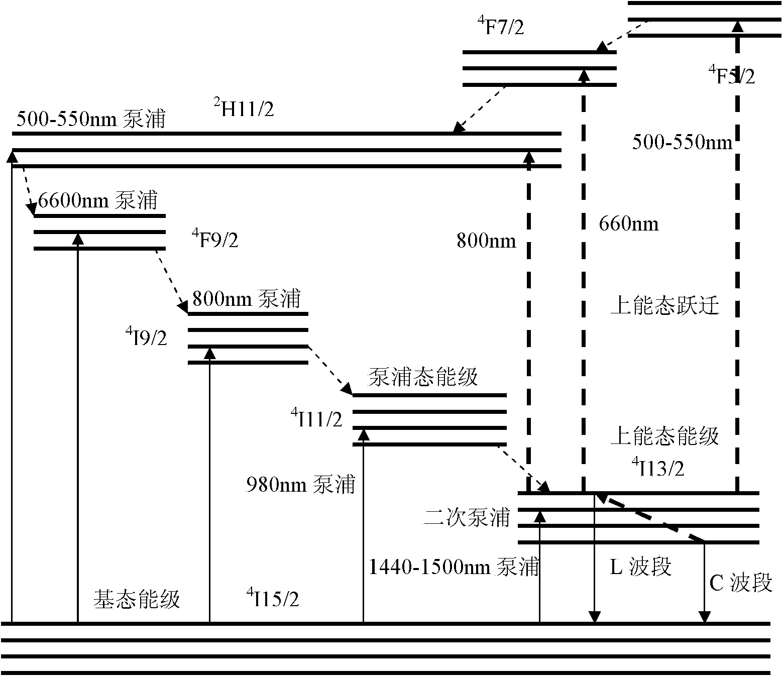
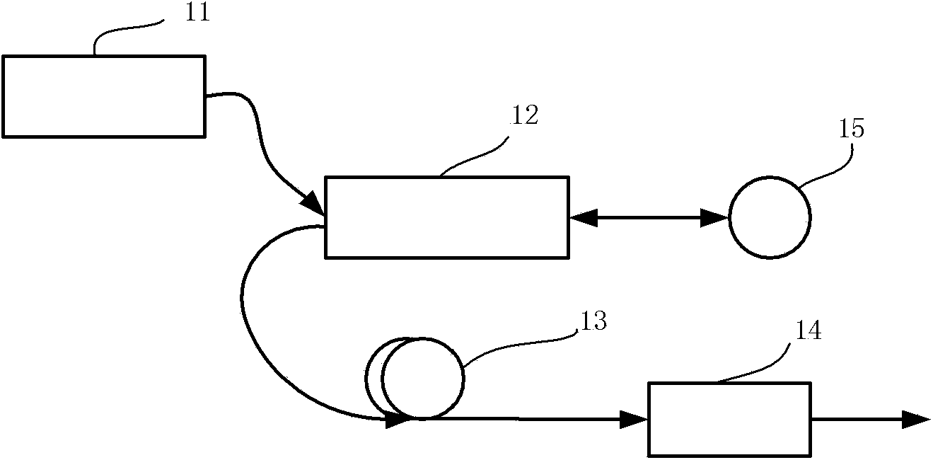
[0060] This embodiment specifically describes the implementation of the L-band light source of the present invention. The structure diagram is as figure 2 Shown. The 980nm pump laser output by the first pump laser is input through the 980nm first port of the first wavelength division multiplexer, and output from the third port (980nm+1550nm) of the first wavelength division multiplexer and then passes through the broadband reflector , Enter the second port (1550nm) of the first wavelength division multiplexer, generate from the erbium-doped fiber 4 I 13 / 2 Energy level to ground state ( 4 I 15 / 2 ) The transition of the energy level, as the length of the first erbium-doped fiber gradually increases, the generated fluorescence produces a secondary pumping and transitions to 4 I 13 / 2 Energy level, under the effect of the Stark effect, the fluorescence wavelength of the second transition shifts to the long wavelength direction, resulting in L-band fluorescence....

Example Embodiment

[0061] Example 2

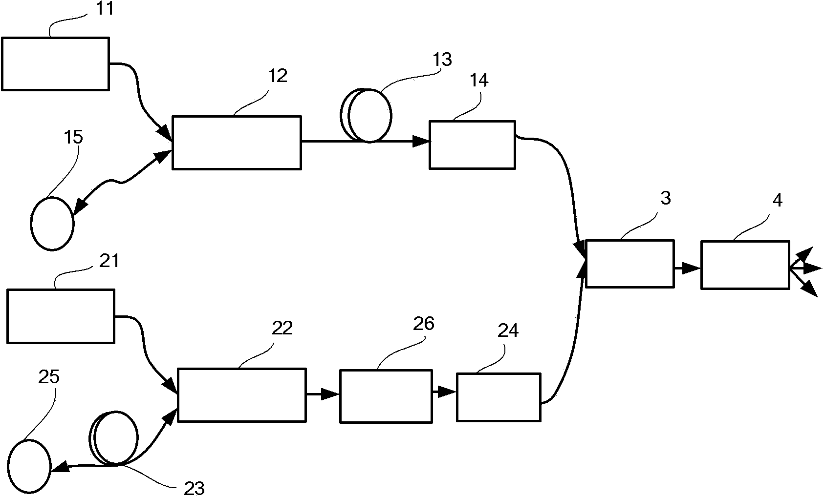
[0062] This embodiment specifically describes the implementation of the L+C band light source of the present invention. The structure diagram is as image 3 Shown. The C-band light source adopts the double-pass backward method. The 980nm pump laser output by the second pump laser is input through the first port (980nm) of the second wavelength division multiplexer, and from the third wavelength division multiplexer. After the output of the port (980nm+1550nm), fluorescence is generated through the second erbium-doped fiber. A fiber reflector is connected behind the second erbium-doped fiber. The unpumped 980nm light returns to the second erbium-doped fiber through the reflector and is pumped again. Improve the pumping efficiency, and the generated 1550nm fluorescence is output through the second port (1550nm) of the second wavelength division multiplexer to form a C-band spectrum. Because the gain coefficient and absorption coefficient of erbium-doped fiber ne...


PUM

PropertyMeasurementUnit
Light intensityaaaaaaaaaa

Abstract

The invention discloses a wide-spectrum light source for a fiber-optic gyroscope and a manufacturing method of the wide-spectrum light source. The light source can be an L-wave-band light source or a C+L-wave-band light source. Both the L-wave-band light source structure and the C-wave-band light source structure comprise pump lasers, optical fiber wavelength division multiplexers, er-doped optical fibers, optical fiber isolators and optical fiber reflectors. The C-wave-band light source structure is similar to the L-wave-band light source structure. The L-wave-band light source or the C+L-wave-band light source can be cascaded through a 1*3 optical fiber coupler. According to the wide-spectrum light source for the fiber-optic gyroscope and the manufacturing method of the wide-spectrum light source, a full-optical-fiber device is adopted, the wide-spectrum light source is easy to manufacture, miniaturization is facilitated and the wide-spectrum light source has the advantages of being wide in spectrum of the light source, high in power output, good in stability of wavelength, free of polarized radiation, not sensitive to ultraviolet ray, low in cost, long in service life and the like.

Description

technical field [0001] The invention belongs to the fields of fiber optic gyroscopes and fiber optic sensors, and in particular relates to a wide-spectrum light source for fiber optic gyroscopes and a manufacturing method thereof. Background technique [0002] In fiber optic gyroscopes, the requirement for the light source is generally low temporal coherence. At present, the single-axis fiber optic gyroscope with medium and low precision mainly uses superluminescent light-emitting diode (SLD) as the light source, but SLD has the disadvantages of low output power, poor wavelength stability, short life and poor spatial coherence. subject to many restrictions. The broadband light source made of superfluorescent fiber optic light source (SFS) has the advantages of relatively high output power, low time coherence and good temperature stability, and has a very important application in the field of fiber optic gyro. [0003] The sensitivity limit of the fiber optic gyroscope depe...

Claims


Application Information

Patent Timeline
IPC IPC(8): H01S3/067G01C19/72
Inventor 徐建明郑吉兵施洋张超马衍宇
Owner 中国兵器工业导航与控制技术研究所
Why Eureka
Try Eureka