Integrally formed radiator of semiconductor light source lamp and manufacturing method thereof

A manufacturing method and radiator technology, which are applied to the cooling/heating devices of lighting devices, lighting and heating equipment, lighting devices, etc., can solve the problems of complex radiator manufacturing processes, complex radiator manufacturing processes, and unstable thermal conductivity. , to achieve the effect of light weight, improved heat dissipation effect and good heat dissipation effect

Inactive Publication Date: 2014-01-22
许富昌
View PDF8 Cites 4 Cited by
  • Summary
  • Abstract
  • Description
  • Claims
  • Application Information

AI Technical Summary

Problems solved by technology

[0002] At present, the heat sinks of semiconductor light source lamps and lanterns on the market have different shapes. Most of the heat sinks are manufactured by aluminum die-casting molding process and extrusion profile cutting process. The thermal conductivity is low, the weight of the heat sink is large, the consumables are many, and the post-processing is complicated. , low production efficiency and high production cost
[0003] The current radiator base plate and cup body are processed separately and then fastened. This superimposed method makes the thermal conductivity unstable and the thermal conductivity is not good. During the production process, there is a process of fixing the two components together.
[0004] The disadvantage of the prior art is that the manufacturing process of the radiator is complex, such as the manufacturing method of the finned radiator, which includes the following steps: material preparation step, alignment step, stamping step, pressing and bending step, cutting and riveting step, rotating step ﹑Repeat the steps of breaking and riveting and the steps of rotating and taking out. More specifically, a metal strip is continuously stamped on a processing machine to form heat dissipation fins, and the heat dissipation fins are cut from the metal strip in sequence. Then insert them into the slots of a metal substrate in sequence, and use two-way riveting to sequentially fix the cooling fins on the metal substrate to obtain a heat sink
The manufacturing process of the radiator is complicated, and the single product takes a long time. Because it is contact heat conduction, its heat dissipation effect is average.

Method used


Image

  • Integrally formed radiator of semiconductor light source lamp and manufacturing method thereof
  • Integrally formed radiator of semiconductor light source lamp and manufacturing method thereof
  • Integrally formed radiator of semiconductor light source lamp and manufacturing method thereof

Examples


Embodiment 1

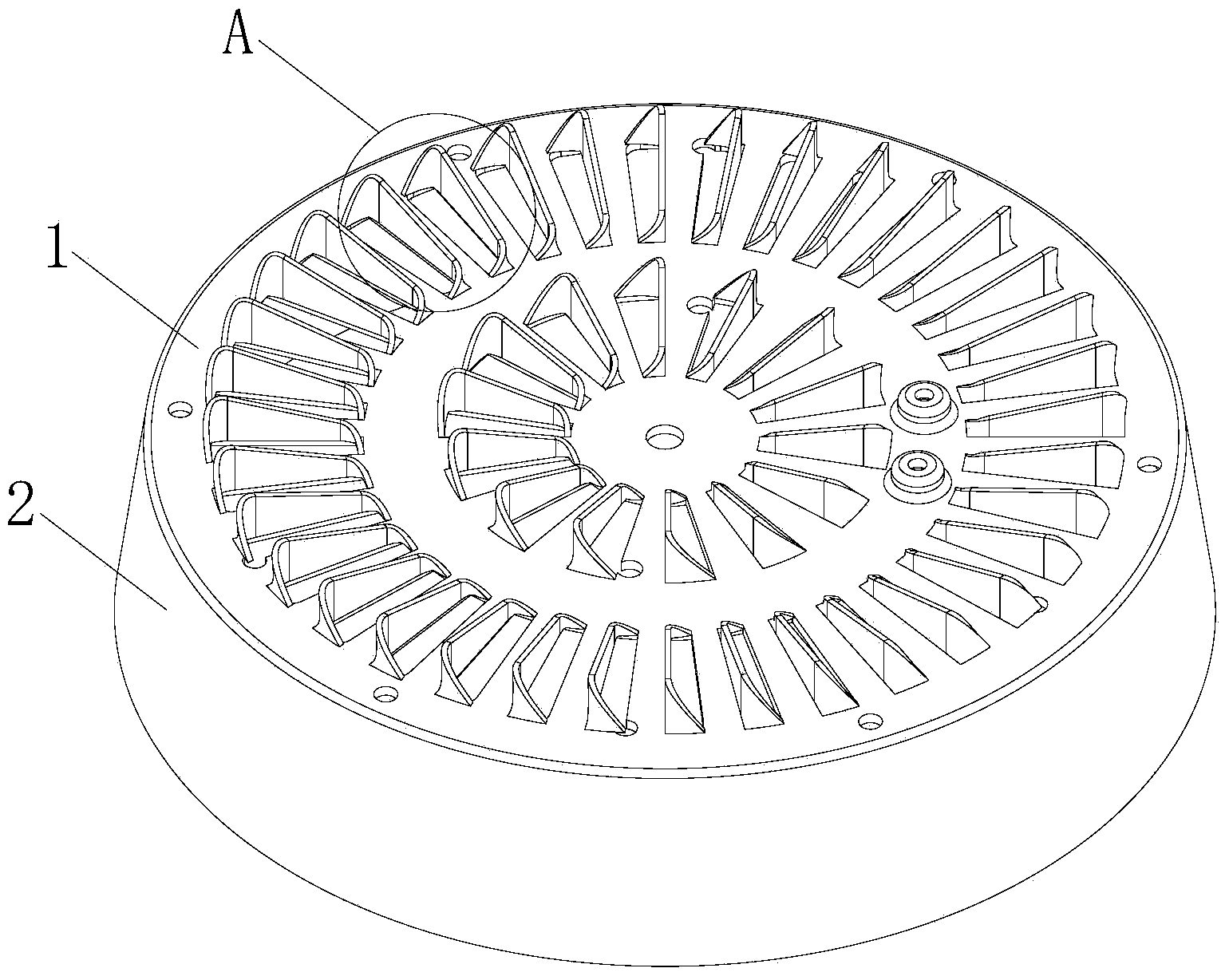
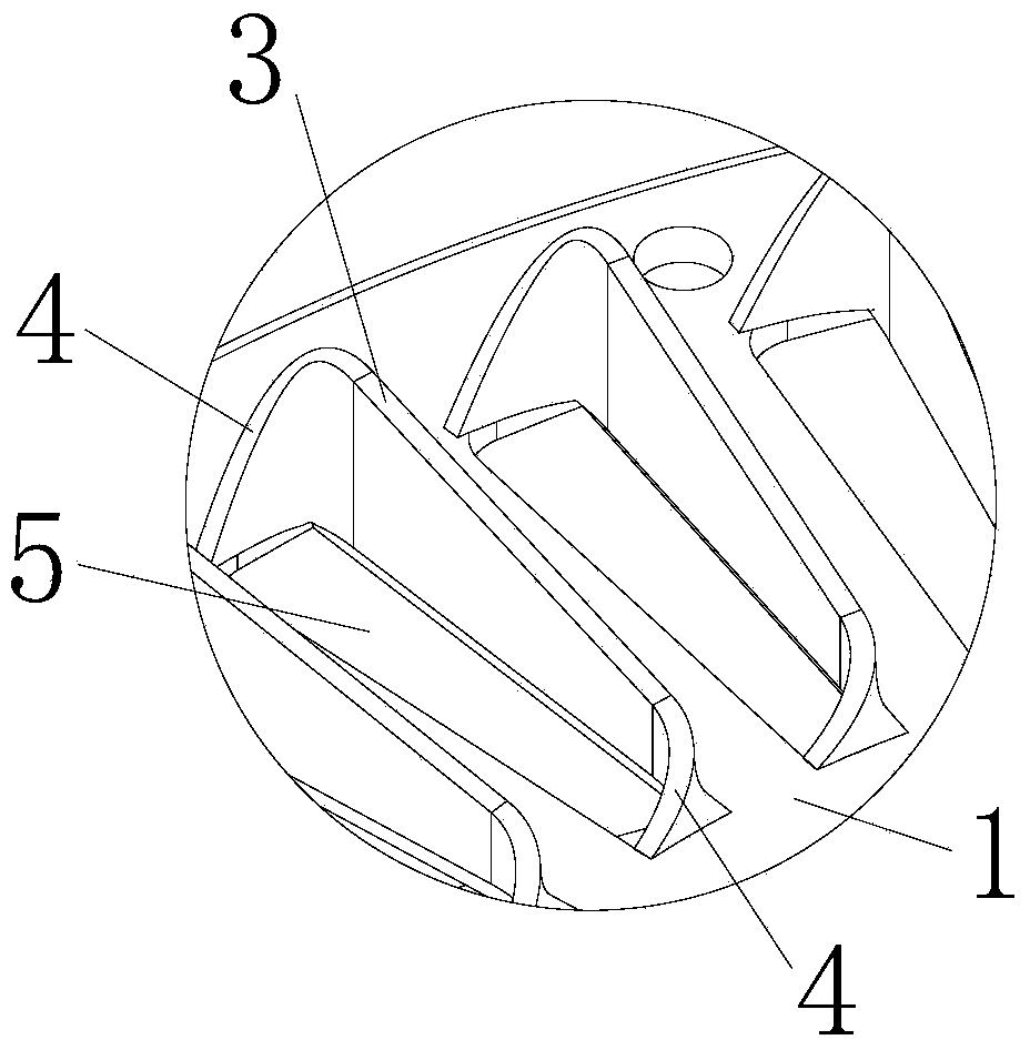
[0042] see figure 1 and figure 2 As shown, the integrally formed heat sink of the semiconductor light source lamp of the embodiment of the present invention includes a substrate 1 and a cup body 2. The substrate 1 is stretched out of the cup body 2 through a spinning process, and then the cup body 2 is The excess part is cut off to make the cup body 2 into a barrel shape, and the base plate 1 is twisted by metal stamping and partially raised upwards to form heat dissipation blades 3 with pull-away pieces 4, and the heat dissipation blades 3 are raised upwards to form air holes 5. On the base plate 1, there are 14 first circular arrangements and 36 heat dissipation blades 3 that are stamped and twisted to the outside of the radiator, and the pull-off sheet 4 increases the 1 The contact area with the heat dissipation fins 3, the heat dissipation fins 3 and the substrate 1 are vertically distributed, combining the characteristics of heat dissipation upwards, thereby acceleratin...

Embodiment 2

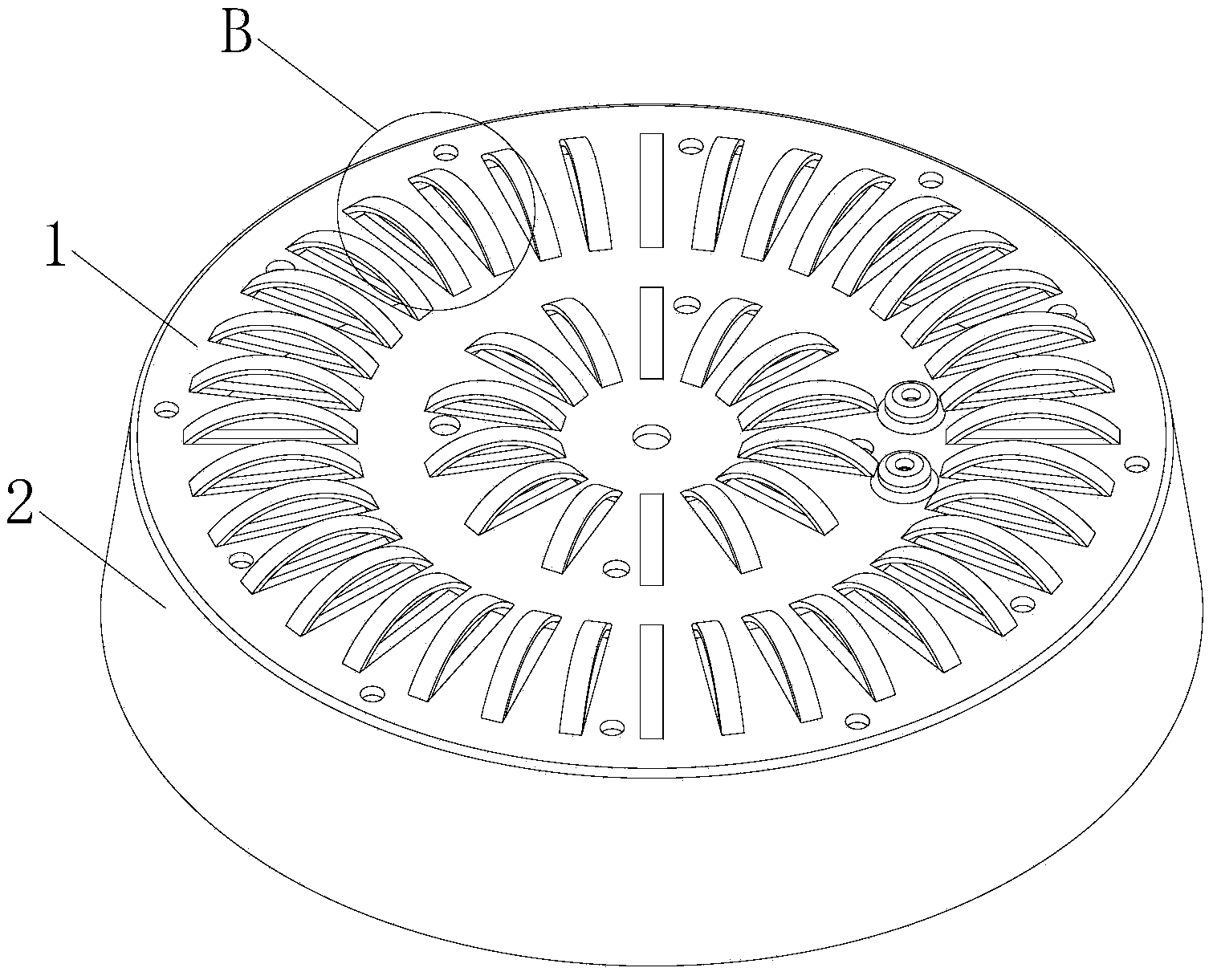
[0046] see image 3 and Figure 4 As shown, the integrally formed heat sink of the semiconductor light source lamp of the embodiment of the present invention includes a substrate 1 and a cup body 2. The substrate 1 is stretched out of the cup body 2 through a spinning process, and then the cup body 2 is The excess part is cut off to make the cup body 2 into a barrel shape, and the base plate 1 is partially raised upwards to form arc-shaped cooling fins 6 after being twisted by metal stamping, and the arc-shaped cooling fins 6 are raised upwards to form the ventilation holes 5 . On the base plate 1, there are 14 arc-shaped cooling fins 6 arranged in a first circular arrangement and 36 arc-shaped cooling fins 6 that are stamped and twisted toward the outside of the radiator.

Embodiment 3

[0048] see Figure 5 and Figure 6 As shown, the integrally formed heat sink of the semiconductor light source lamp of the embodiment of the present invention includes a substrate 1 and a cup body 2. The substrate 1 is stretched out of the cup body 2 through a spinning process, and then the cup body 2 is The excess part is cut off to make the cup body 2 into a barrel shape, and the base plate 1 is stamped with metal to form vent holes 5. There are 14 holes arranged in a first circle on the base plate 1, and 14 holes are arranged in a second circle on the base plate 1. 36 ventilation holes 5 are provided.


PUM


Abstract

The invention discloses an integrally formed radiator of a semiconductor light source lamp. The radiator comprises a substrate and a cup body, wherein the substrate and the cup body are integrally formed, a plurality of sheet strips are punched on the substrate, tail ends of the sheet strips are not disengaged from the substrate, strip-shaped holes are formed between the substrate and the sheet strips, and a light source is fixed to the substrate. The strip-shaped holes form circulation air holes or air discharge grooves of the radiator. A manufacturing method of the integrally formed radiator of the semiconductor light source lamp comprises the four steps of blanking, stretching, edge cutting and sheet strip punching. The radiator is simple in manufacturing process, easy to form and process at one time, little in amount of waste materials in the twisting process, high in material utilization rate and low in production cost; the radiator has a high heat conductivity coefficient and a good radiating effect and achieves radiating of the high-power LED lamp; the radiator is of a disc shape, the radiating sheet strips formed through punching and twisting are not disengaged from the substrate, and heat conduction is facilitated.

Description

technical field [0001] The invention relates to a radiator in the field of lighting fixtures and a manufacturing method thereof. More specifically, the present invention relates to an integrated heat sink for a semiconductor light source lamp and a manufacturing method thereof. Background technique [0002] At present, the heat sinks of semiconductor light source lamps and lanterns on the market have different shapes. Most of the heat sinks are manufactured by aluminum die-casting molding process and extrusion profile cutting process. The thermal conductivity is low, the weight of the heat sink is large, the consumables are many, and the post-processing is complicated. , low production efficiency and high production cost. [0003] The current radiator base plate and cup body are processed separately and then fastened. This superimposed method makes the thermal conductivity unstable and the thermal conductivity is not good. During the production process, there is a process o...

Claims


Application Information

Patent Timeline
Patent Type & Authority Applications(China)
IPC IPC(8): F21V29/00B23P15/26F21V29/77
Inventor 许富昌
Owner 许富昌
Why Eureka
Try Eureka