
Wireless monitoring device and blood pressure detecting device

A monitoring device and detection device technology, applied in the directions of diagnostic recording/measurement, medical science, signal transmission system, etc., can solve the problems of increasing detection error, small contact area between the sensor unit and the skin surface, discomfort, etc., to reduce labor intensity , The effect of reliable blood pressure value and wide application range

Inactive Publication Date: 2014-02-12
许建平
View PDF1 Cites 13 Cited by
  • Summary
  • Abstract
  • Description
  • Claims
  • Application Information

AI Technical Summary

Problems solved by technology

[0002] At present, known devices of the same kind similar to the monitoring device of the present invention are called: monitors, and existing monitors can also monitor pulse, heart rate, blood pressure, electrocardiogram, body temperature, etc. At night, when the guardian is tired and sleeping soundly, when the patient's condition is critical, the defect of not being able to wake up the guardian in time, the bigger problem will cause the serious accident that the patient's life is irreversible
[0003] At present, the known non-invasive and inflation-free dynamic or continuous blood pressure monitoring equipment is to install the sensor unit on the belt, and the sensor unit compresses the surface of the arterial blood vessel skin to partially occlude the arterial blood vessel to detect the blood pressure. The disadvantages are: the sensor unit The pressure of the unit pressing the arterial skin surface cannot be precisely controlled, and the sensor unit cannot generate a large signal amplitude. Due to the limitations of the sensitivity, resolution, error rate, and range of the signal processing unit, the lower signal amplitude will cause detection. The increase of the error, especially when the air temperature and body temperature change, this situation will become more obvious; in order to solve the above problems, the binding force of the belt can be increased, but with the increase of the binding force, the user will wear it for a long time It is very uncomfortable, and the bigger problem is that it will damage the skin tissue of the user's wrist; however, the smaller binding force of the band will increase the detection error; in addition, the existing blood pressure monitoring equipment also has a contact area between the sensor unit and the skin surface Small, the defect that the sensor unit cannot produce a large signal amplitude; in addition, in the existing blood pressure monitoring equipment, the sensor unit cannot accurately press on the part of the arterial skin surface that changes the most with the pulse or blood pressure, or, in the When the living body moves, when the blood pressure monitoring equipment is repeatedly worn, the position of the sensor unit relative to the skin surface of the artery will change. Due to the change of the position of the sensor unit relative to the skin surface, the blood pressure data will change. Although some blood pressure monitoring equipment proposes However, when the blood pressure monitoring device is transferred to other users, or when the user removes the stabilization pad and then reuses it, the blood pressure data of the blood pressure device must be calibrated again. For non-professional For professionals, it is not easy to calibrate blood pressure equipment cumbersomely. Therefore, the existing non-invasive and inflation-free dynamic or continuous blood pressure monitoring equipment is inconvenient for repeated use, and the blood pressure measurement data is sometimes unreliable.

Method used


Image

  • Wireless monitoring device and blood pressure detecting device
  • Wireless monitoring device and blood pressure detecting device
  • Wireless monitoring device and blood pressure detecting device

Examples


Embodiment Construction

[0055] The present invention is illustrated below in conjunction with the accompanying drawings.

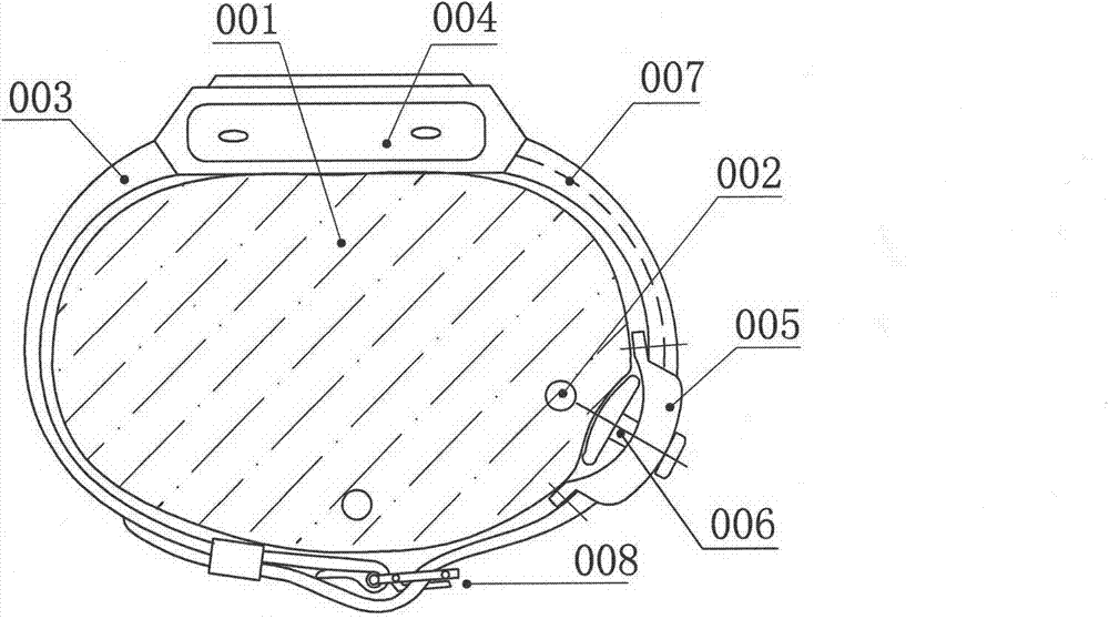
[0056] figure 1 It is a schematic diagram of a continuous or ambulatory blood pressure monitoring watch implemented by the present invention; wherein, 001 is the human wrist, 002 is the radial artery blood vessel, 003 is a belt, and 005 is a part of the belt, which is formed along the length direction of the belt. Bending from inside to outside, referred to as bending parts in the following examples of the present invention, the shape of the bending parts can be concave, ∩, Ω, etc.; 006 is the sensor unit, 004 is the built-in MCU, functional circuit, display screen, The case of the battery, etc., 007 is the wire that connects the sensor unit to the internal circuit of the case, and 008 is the buckle. It can be seen from the figure that the sensor unit 006 is arranged inside the curved part 005, and when the curved part 005 is attached to the upper and both sides of the skin surf...


PUM


Abstract

The invention discloses a wireless monitoring device. The wireless monitoring device comprises a wireless transmission unit, a signal processing unit, a tying band and a vibrating unit arranged on the tying band. A blood pressure detecting device comprises a sensor unit, a signal processing unit and a tying band, wherein at least one part of the tying band comprises a part which bends from the side close to the limbs to the outer side in the length direction of the tying band, the sensor unit is arranged on the inner side of the bend part and at least comprises two sensor elements, a preset included angle is formed between the vertical lines of the sensitive faces of the sensor elements, and a movable connecting component is arranged between the sensor unit and the tying band. According to the blood pressure detecting device, signals which are changed along with changes of pulse or changes of the blood pressure can be accurately obtained within a large detecting range, and blood pressure detecting values are stable and reliable.

Description

Technical field [0001] The invention relates to a monitor worn on the body of a guardian to monitor pulse, heart rate, respiration, blood pressure, electrocardiogram, body temperature, blood sugar, blood oxygen saturation, fetal heart rate of pregnant women, baby crying at night, baby diaper humidity, patient call , Earthquake, fire, anti-theft and other physiological parameters related to vital signs or physical parameters for wireless monitoring or reminders, and wireless monitoring devices that can be used in conjunction with the wireless monitoring device, through the contact of the sensor unit with the skin surface of the living body, dynamic or The device for continuous pulse or blood pressure detection belongs to the field of electronic security products, electronic health products and medical equipment, but it is not limited thereto. Background technique [0002] At present, known devices of the same kind similar to the monitoring device of the present invention are ...

Claims


Application Information

Patent Timeline
Patent Type & Authority Applications(China)
IPC IPC(8): A61B5/00A61B5/0225G08C17/02
Inventor 许建平
Owner 许建平
Learn More