
PM2.5 feeding system and method thereof

A feeding system and feeding technology, applied in the field of aerosol particle generation system, can solve the problems of poor control of gas flow, lack of selectivity of particle size, easy to destroy the physical and chemical characteristics of particles, etc., and achieve stable system running time Longer, reduce the concentration of cutting particles, and broaden the effect of cleaning cycle

Active Publication Date: 2015-04-29
ZHEJIANG UNIV
View PDF3 Cites 0 Cited by
  • Summary
  • Abstract
  • Description
  • Claims
  • Application Information

AI Technical Summary

Problems solved by technology

Among them, the screw feeding system and the vibrating feeding system make the particles enter the pipeline to form aerosol through the screw rotation and vibration respectively, and the negative pressure suction injection system directly sucks the particles into the pipeline by forming a negative pressure state. Forming aerosols, all three can form stable aerosols to a certain extent, but the disadvantage is that they lack selectivity for particle size and cannot form aerosols with specific particle size requirements
The fluidized bed feeding system is to blow a certain flow of gas at the bottom of the bed, and through the action of air force and the gravity of the particles themselves, the particles will keep rolling up and down, and finally the particles with smaller mass will escape to form aerosol. This technology In theory, it is selective to particles, but in actual operation, the input gas flow cannot be well controlled, and it is easy to cause the escape of large particles
The water vapor evaporation carrying technology is to soak the particles in the liquid phase, heat the liquid phase so that the liquid phase carries part of the particles during the evaporation process, and then dry the liquid phase in the later stage to obtain the dry particle state. This technology can obtain particle However, it is easy to destroy the original physical and chemical properties of the particles during the process of particle infiltration and the process of drying the liquid phase in the later stage

Method used


Image

  • PM2.5 feeding system and method thereof

Examples


Embodiment Construction

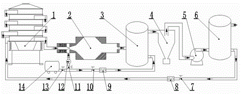
[0019] Such as figure 1 Shown, PM 2.5 The feeding system includes vibrating screen feeder 1, aerosol duster 2, aerosol buffer tank and diluter 3, PM 2.5 Separator 4, induced draft fan 5, aerosol buffer tank 6, return air flow control valve 7, return air flow meter 8, diluter compressed air supply flow meter 9, diluter compressed air supply control valve 10, dust Jet air pressure control valve 11, dust blower jet air pressure gauge 12, air compressor supply air flow control valve 13, air compressor 14; among them, vibrating screen feeder 1, aerosol dust blower 2, aerosol buffer tank and dilution Device 3, PM 2.5 The separator 4, the induced draft fan 5, and the aerosol buffer tank 6 are connected in sequence, the aerosol buffer tank 6 returns the outlet, the return air flow control valve 7, the return air flow meter 8, the vibrating screen feeder 1 the bottom vibrating screen The air inlets of the stages are connected in sequence, and the airflow given by the air compressor ...


PUM


Abstract

The invention discloses a PM2.5 feeding system and a method thereof. A vibrating screen feeder, an aerosol dust raising device, an aerosol buffer tank and diluter, a PM2.5 separator, a draught fan and an aerosol buffer tank are sequentially connected; a returning charge outlet of the aerosol buffer tank, a returning charge air flow control valve, a returning charge air flow meter and a vibrating-screen-level gas inlet at the bottommost layer of the vibrating screen feeder are sequentially connected; air flow supplied by the air compressor is divided into two ways by an air supplying air flow control valve of the air compressor, one way of the air flow is connected with an air inlet of the aerosol buffer tank and diluter through a diluter compressed air supplying control valve and a diluter compressed air supplying air flow meter, and the other way of the air flow is connected with an air inlet of the aerosol dust raising device through a dust raising device jet flow air pressure control valve and a dust raising device jet flow air pressure meter. According to the invention, mineral particles or carbonaceous particles which are collected actually act as particle sources, so that higher-concentration PM2.5 aerosol is generated automatically, continuously and stably, and the aerosol can be cut with accurate particle size.

Description

technical field [0001] The invention relates to an aerosol particle generating system, in particular to a PM 2.5 Feeding system and method thereof. Background technique [0002] The aerosol particle generation system can not only be used for the study of the physical and chemical characteristics of particles, the charging mechanism of particles, and the mechanism of condensation and removal of particles, but also plays an important role in the research of simulating the atmospheric environment and simulating the flue gas environment of power plants. At present, the aerosol particle generation system is mainly divided into two types of technology, one uses combustion to directly generate particles, and the other uses collected dust particles as a particle source for particle dusting. [0003] In the technology of directly generating particles by combustion, carbon black particles are mainly generated by burning methane or propane gas with oxygen. This aerosol has small parti...

Claims


Application Information

Patent Timeline
Patent Type & Authority Patents(China)
IPC IPC(8): B01J13/00
Inventor 骆仲泱江建平方梦祥王涛郑成航施正伦倪明江岑可法
Owner ZHEJIANG UNIV
Learn More