
Full-numerical-control spiral bevel gear milling machine

A technology of spiral bevel gears and gear milling machines, which is applied in gear tooth manufacturing devices, gear cutting machines, belts/chains/gears, etc., which can solve the loss of transmission accuracy and transmission efficiency, the speed limit of tool spindle movement, and the influence of bevel gear machining accuracy. and other problems, to achieve the effect of improving machining accuracy and smoothness, simplifying transmission structure, improving transmission accuracy and transmission stability

Active Publication Date: 2014-02-12
通用技术集团天津第一机床有限公司
View PDF7 Cites 11 Cited by
  • Summary
  • Abstract
  • Description
  • Claims
  • Application Information

AI Technical Summary

Problems solved by technology

This will not only lose transmission accuracy and transmission efficiency, but also limit the movement speed of the tool spindle
Due to the limitation of the tool spindle structure of the above-mentioned gear milling machine, at present, only the intermittent indexing method can be used to process spiral shrinking bevel gears and hypoid gears, but the continuous indexing method cannot be used to process cycloidal contour bevel gears and hypoid gears gear
Although the second-generation tool spindle structure using gear transmission has appeared in the past year, due to the influence of the machining accuracy of the gear itself, transmission errors are prone to occur, which in turn affects the machining accuracy of bevel gears.

Method used


Image

  • Full-numerical-control spiral bevel gear milling machine
  • Full-numerical-control spiral bevel gear milling machine
  • Full-numerical-control spiral bevel gear milling machine

Examples


Embodiment Construction

[0036] In order to further understand the invention content, characteristics and effects of the present invention, the following examples are given, and detailed descriptions are as follows in conjunction with the accompanying drawings:

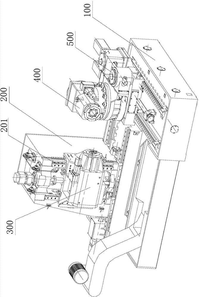
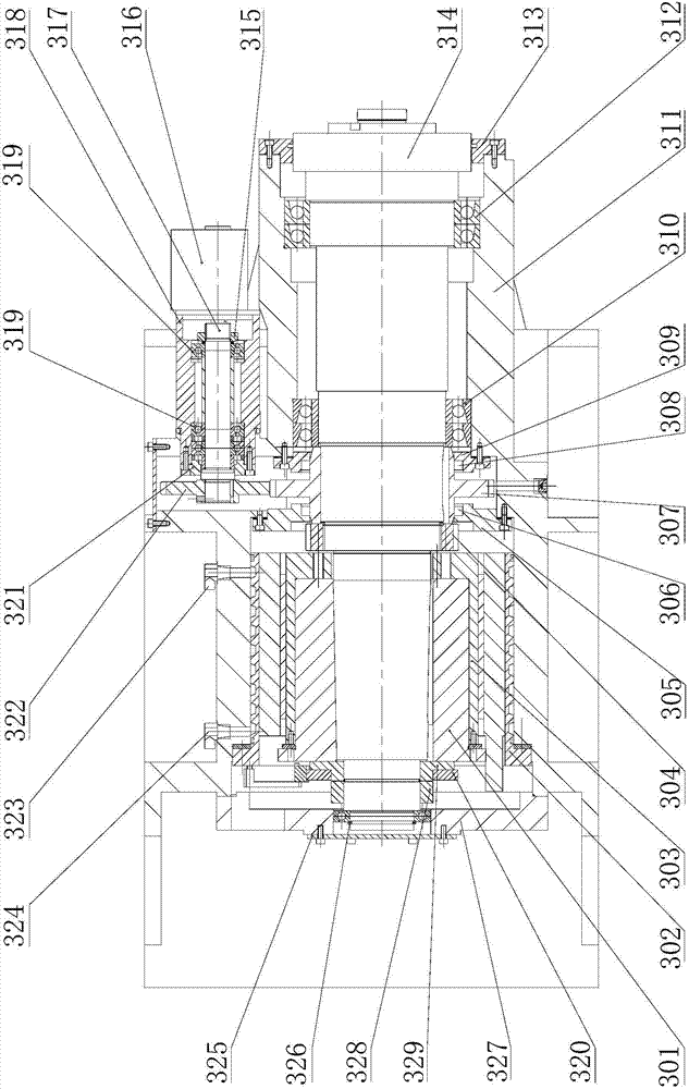
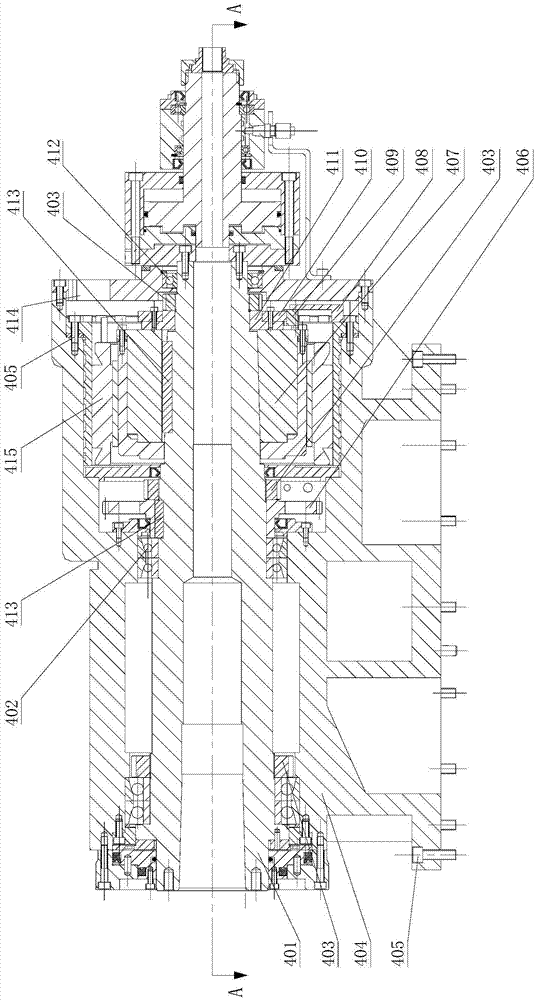
[0037] see Figure 1-Figure 9 , full CNC spiral bevel gear milling machine, including bed 100, column 200, tool box 300, workpiece box 400, turntable drive 500, electrical system, pneumatic system, hydraulic system and cooling system. Two pairs of horizontal and mutually perpendicular linear guide rails are arranged on the bed 100, a pair of linear guide rails 201 perpendicular to the bed guide rails and parallel to each other are fixed on the column, and the column and the turntable transmission device are respectively arranged on the bed on the linear guide. The tool box 300 is hung on the linear guide rail 201 on the outer side of the column, and the tool box includes a tool spindle box and a tool spindle arranged in the tool spindle box....


PUM


Abstract

The invention relates to a full-numerical-control spiral bevel gear milling machine. The full-numerical-control spiral bevel gear milling machine comprises a lathe bed, a stand column, a tool box, a workpiece box, a rotary table transmission device, an electric system, a pneumatic system, a hydraulic system and a cooling system. The full-numerical-control spiral bevel gear milling machine is characterized in that a machine tool spindle torque motor rotor is connected with a machine tool spindle, the machine tool spindle is provided with a spindle damping mechanism, one end of a workpiece spindle is directly fastened with the machine tool spindle torque motor rotor, a workpiece spindle clamping mechanism is arranged at the other end of in a box body of the workpiece box, the workpiece spindle is provided with a workpiece spindle damping mechanism, and the rotary table transmission device comprises a worm wheel bottom sleeve, a worm wheel and worm pair, a rotary table oscillating bar mechanism, a rotary table clamping oil cylinder and a supporting base. The full-numerical-control spiral bevel gear milling machine has the advantages that a torque motor is adopted to serve as power to directly drive the machine tool spindle and the workpiece spindle, the transmission precision and the machining efficiency can be improved greatly, adjustment is convenient, and the rigidity is good; due to driving of the worm wheel and worm pair, the adjustment on the root angle of the workpiece box and the large rotation of feeding and discharging are achieved, and the rotary table oscillating bar mechanism achieves the finish machining of a small gear wheel matched with a forming-method big gear wheel and the machining of a cycloid gear.

Description

technical field [0001] The invention belongs to the technical field of bevel gear processing machine tools, in particular to a fully numerically controlled spiral bevel gear milling machine. Background technique [0002] The design of the spiral bevel gear of the automobile drive axle mainly adopts two tooth systems: tapered teeth and cycloidal teeth. Tapered gear is a traditional main processing method, which has been widely used at home and abroad for a long time. In recent years, the design calculation and processing adjustment of cycloidal gears have been greatly simplified, and the adjustment of the contact area is also simpler and faster, and the bearing capacity of cycloidal gears is also higher. In the automobile industry at home and abroad, cycloidal gears are more and more widely used. Therefore, machine tools that can process both tapered and cycloidal teeth are becoming more and more popular. [0003] Due to the principle of processing cycloidal teeth, it is r...

Claims


Application Information

Patent Timeline
IPC IPC(8): B23F9/08B23F23/00B23Q5/10B23Q5/20B23Q11/12
Inventor 沈凤美王秀梅陈志伟李佳陈洁王伟柴宝连吴杰王威
Owner 通用技术集团天津第一机床有限公司
Learn More