
Method and device for antenna beam alignment

An antenna beam and alignment technology, which is applied to antennas, antenna components, wireless communications, etc., can solve the problems of reduced data transmission capacity of transmission links, increased path loss, narrow beams, etc., to reduce the establishment of data transmission connections Time, the effect of keeping the link continuous

Inactive Publication Date: 2014-02-19
ZTE CORP
View PDF4 Cites 45 Cited by
  • Summary
  • Abstract
  • Description
  • Claims
  • Application Information

AI Technical Summary

Problems solved by technology

This configuration method has obvious shortcomings. For example, because the beam is too narrow and the channel fading is too large, when the two beams are not aligned, the link from the transmitter to the receiver may be interrupted, resulting in the inability of the antennas at both ends to communicate. Information exchange and beam direction pairing based on this; as another example, since both the transmitting end and the receiving end need to perform beam scanning, assuming that the antenna beams at each end have N adjustable orientations, the antenna beams at both ends have a total of N 2 possible combinations, and the optimal combination requires N 2 Scans can be found, which will undoubtedly increase the delay in establishing a connection
Even if the optimal transmission path between the transmitter / receiver is found and established through the above method of beam direction step scanning, there may be situations where people or other objects are blocked in the middle of the transmission path. In this case, it is equivalent to Strong shadow fading occurs in the middle of the transmission path, and the significantly increased path loss caused by shadow fading will lead to a sharp decline in the data transmission capacity of the existing transmission link or even interrupt the existing data transmission channel
[0005] For the problem of using narrow beam antennas to establish communication links in related technologies, no effective solution has been proposed so far

Method used


Image

  • Method and device for antenna beam alignment
  • Method and device for antenna beam alignment
  • Method and device for antenna beam alignment

Examples


Embodiment 1

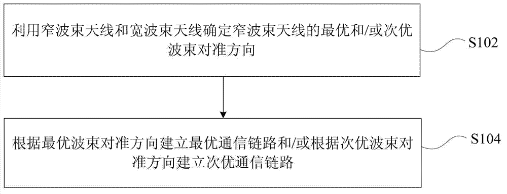
[0036] An embodiment of the present invention provides an antenna beam alignment method, wherein the local end is configured with a narrow beam antenna and a wide beam antenna, and the opposite end is configured with a narrow beam antenna and a wide beam antenna. figure 1 is a flowchart of an antenna beam alignment method according to an embodiment of the present invention, such as figure 1 As shown, the process includes the following steps:

[0037] Step S102, using the narrow beam antenna and the wide beam antenna to determine the optimal and / or suboptimal beam alignment direction of the narrow beam antenna;

[0038] Step S104, establishing an optimal communication link according to an optimal beam alignment direction and / or establishing a suboptimal communication link according to a suboptimal beam alignment direction.

[0039] Through the above steps, the narrow-beam antenna and wide-beam antenna are configured on the local end, and the narrow-beam antenna and wide-beam a...

Embodiment 2

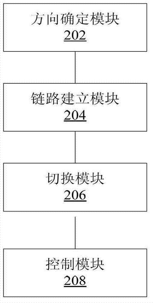
[0053] An embodiment of the present invention also provides an antenna beam alignment device, which is used to implement the above-mentioned embodiments and preferred implementation modes, and what has already been described will not be repeated. As used below, the term "module" may be a combination of software and / or hardware that realizes a predetermined function. Although the devices described in the following embodiments are preferably implemented in software, implementations in hardware, or a combination of software and hardware are also possible and contemplated.

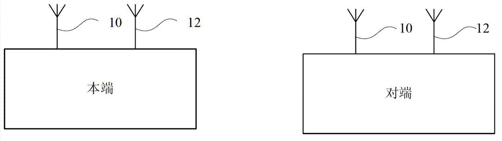
[0054] The antenna beam alignment device in this embodiment is located at the local end and the opposite end, and the specific antenna configuration diagram is as follows Figure 1a As shown, the narrow beam antenna 10 and the wide beam antenna 12 are configured at the local end, and the narrow beam antenna 10 and the wide beam antenna 12 are configured at the opposite end.

[0055] figure 2 is a structural...

Embodiment 3

[0068] In this embodiment, the transmitting end and the receiving end may correspond to the local end or the opposite end. When the transmitting end corresponds to the local end, the receiving end corresponds to the opposite end; when the transmitting end corresponds to the opposite end, the receiving end corresponds to the local end.

[0069] image 3 is one of the flow charts of the antenna beam alignment method according to the preferred embodiment of the present invention, such as image 3 As shown, the process includes the following steps:

[0070] Step S302, the transmitting end transmits a low data rate (Low Data Rate, LDR for short) access signal.

[0071] The transmitting end uses a low-gain wide-beam antenna to send a low-rate access signal to the receiving end, and waits for the receiving end to respond.

[0072] Step S304, the receiving end responds to the low-rate access signal.

[0073] The low-gain wide-beam antenna at the receiving end is in the listening s...


PUM


Abstract

The invention discloses a method and a device for antenna beam alignment. A home terminal is configured with a narrow beam antenna and a broad beam antenna, and an opposite terminal is configured with a narrow beam antenna and a broad beam antenna. The method comprises the steps of determining an optimum beam alignment direction and / or a suboptimum beam alignment direction by using the narrow beam antennas and the broad beam antennas; and establishing an optimum communication link according to the optimum beam alignment direction and / or establishing a suboptimum communication link according to the suboptimum beam alignment direction. According to the invention, the optimum communication link and / or the suboptimum communication link are / is established through using the narrow beam antennas and the broad beam antennas, thereby solving a problem of establishing a communication link by using the narrow beam antennas in relevant technologies, and having the effects of keeping the link being continuous and reducing the time spent on re-establishing data transmission connection.

Description

technical field [0001] The present invention relates to the communication field, in particular, to an antenna beam alignment method and device. Background technique [0002] With the improvement of device manufacturing level and continuous maturity of technology, 60GHz millimeter wave wireless communication technology has gradually moved from theoretical research to practical application. The biggest advantage of 60GHz millimeter wave technology is that the transmission bandwidth is very wide. Near the 60GHz frequency band, it can provide up to 5GHz continuous transmission bandwidth, the transmission rate can reach several Gps, and the working frequency band used can be used without authorization. Since the electromagnetic spectrum is a strong absorption peak near 60 GHz, the propagation attenuation of electromagnetic waves in this frequency range is very large. Therefore, the typical transmission distance of 60 GHz millimeter wave communication technology does not exceed 10...

Claims


Application Information

Patent Timeline
Patent Type & Authority Applications(China)
IPC IPC(8): H04W48/16H04W76/02
CPCH04W48/16H01Q1/1257H01Q3/00H04W16/28
Inventor 陈霖郭阳支周禹忠
Owner ZTE CORP
Features
  • Generate Ideas
  • Intellectual Property
  • Life Sciences
  • Materials
  • Tech Scout
  • Unparalleled Data Quality
  • Higher Quality Content
  • 60% Fewer Hallucinations
Learn More