Non-isolated LED driving circuit
An LED driving and isolation technology, which is applied in the direction of electric lamp circuit layout, electric light source, lighting device, etc., can solve the problem that the LED driving circuit cannot directly use triac dimmers, LED lamp service life limitation, and application circuit design Complicated problems, to achieve long service life, improve service life, reduce electromagnetic interference EMI effect
- Summary
- Abstract
- Description
- Claims
- Application Information
AI Technical Summary
Problems solved by technology
Method used
Image
Examples
Embodiment 1
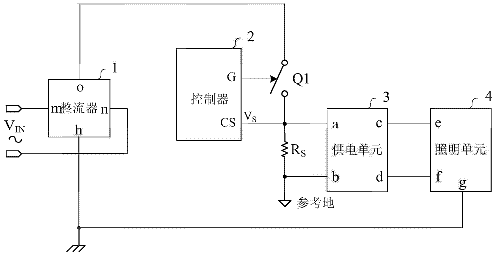
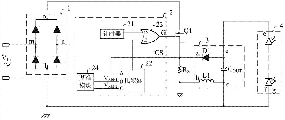
[0035] refer to figure 2 , the controller 2 of this example includes: a timer 21, a comparator 22, a logic gate 23 and a reference module 24; the energy storage unit 3 includes: a diode D1, an inductor L1 and a capacitor C OUT ; The driven unit 4 includes N LED lamps, N≥2; the rectifier bridge 1 adopts a traditional full-bridge rectifier structure; the switching device Q1 adopts an N-type field effect transistor.
[0036] The connection relationship of the various components is as follows:
[0037] The output terminal o of the rectifier bridge 1 is connected to the drain of the N-type field effect transistor, the source of the N-type field effect transistor is connected to the input terminal a of the energy storage unit 3, and the sampling resistor R is passed through the S Connected to the reference ground, the sampling resistor R S The voltage on the sampled signal V S .
[0038] The negative end of the diode D1 is used as the input end a of the energy storage unit 3, a...
Embodiment 2
[0047] refer to Figure 5 , the components used in the rectifier bridge 1, the controller 2, the energy storage unit 3 and the switching device Q1 in this example, and the connection relationship between the components are the same as those in the embodiment 1; the driven unit 4 includes M LED lights , M≥1.
[0048] The M LED lamps are connected in parallel; the positive terminals of the M LED lamps are connected to the output terminal d of the energy storage unit 3; the negative terminal is connected to the output terminal c of the energy storage unit 3; the positive terminals of the M LED lamps or The negative terminal can be used as the ground terminal g. In this example, the negative terminal is selected as the ground terminal g.
[0049] This example works as follows:
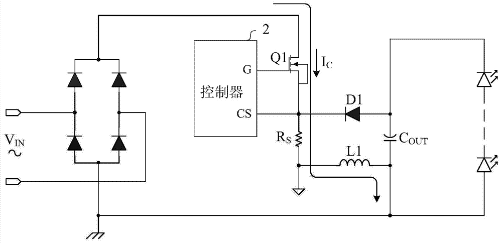
[0050] according to Figure 5 The working current of the given LED driver circuit flows. When the N-type field effect transistor is turned on, the timer 21 starts to count, and the charging current I ...
Embodiment 3
[0052] refer to Image 6 , the components used in the rectifier bridge 1, the controller 2 and the energy storage unit 3 of this example, and the connection relationship between the components are the same as those in the embodiment 1; the driven unit 4 includes H LED lights, H ≥ 3 ; The switching device Q1 adopts an N-type triode.
[0053] The H LED lamps are connected in series and parallel, and the connection methods are various. The connection method selected in this example is: the H-1 LED lamp is connected in parallel with the H-th LED lamp and then connected in series with the remaining H-2 LED lamps; The positive terminal of one LED lamp is connected to the output terminal d of the energy storage unit 3; the negative terminals of the H-1th LED lamp and the Hth LED lamp are connected to the output terminal c of the energy storage unit 3; the H LED lamps The positive terminal or the negative terminal of any one of the LED lamps can be used as the ground terminal g. In t...
PUM
 Abstract
Description
Claims
Application Information
 - R&D
- Intellectual Property
- Life Sciences
- Materials
- Tech Scout
- Unparalleled Data Quality
- Higher Quality Content
- 60% Fewer Hallucinations
Browse by: Latest US Patents, China's latest patents, Technical Efficacy Thesaurus, Application Domain, Technology Topic, Popular Technical Reports.
© 2025 PatSnap. All rights reserved.Legal|Privacy policy|Modern Slavery Act Transparency Statement|Sitemap|About US| Contact US: help@patsnap.com


