Distributed group wave shallow-layer slight shock positioning method based on phase measuring

A phase measurement and distributed technology, applied in the field of blasting vibration testing technology and passive positioning, can solve the problems of frequency dispersion, low signal-to-noise ratio of vibration signals, different waveform propagation speeds, etc., to improve accuracy and reliability, layout The effect of reducing difficulty and ensuring diversity

Active Publication Date: 2014-02-26
ZHONGBEI UNIV
View PDF5 Cites 29 Cited by
  • Summary
  • Abstract
  • Description
  • Claims
  • Application Information

AI Technical Summary

Problems solved by technology

[0005] 1. In the far field of the shock field, the dominant frequency of the shock wave is stable, the group wave velocity is constant, and the superposition of transverse and longitudinal waves is not obvious. Therefore, the accuracy of time difference of arrival (TDOA) positioning is higher when using the arrival time of the first wave of P wave. , in contrast, the constitutive properties of the near-field soil in the vibration field are elastic-plastic, the vibration wave is greatly affected by ground reflection and refraction, and the dispersion phenomenon is serious, that is, the wave propagation speed of different frequency components is different, and the group wave velocity is not a constant value. Therefore, the existing TDOA positioning algorithm cannot be used
[0006] 2. When the vibration sensor is arranged in the near field of the seismic source, due to the different speeds of P wave, S wave and surface wave, the aliasing phenomenon of various vibration waveforms is serious; at the same time, the sensor signal line is coupled with complex electromagnetic interference signals generated by explosions. The signal-to-noise ratio of the vibration signal is low, which makes it impossible to effectively extract the accurate arrival time of the first arrival wave, and the error of the time difference information is large
[0007] Therefore, in shallow underground seismic source location in small areas, it is impossible to use the existing seismic source location method to achieve source location

Method used


Image

  • Distributed group wave shallow-layer slight shock positioning method based on phase measuring
  • Distributed group wave shallow-layer slight shock positioning method based on phase measuring
  • Distributed group wave shallow-layer slight shock positioning method based on phase measuring

Examples


Embodiment Construction

[0041] The technical solution of the present invention will be described in detail below in conjunction with the accompanying drawings.

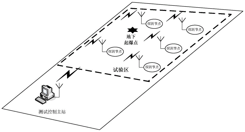
[0042] Such as figure 1 The distributed seismic source test system shown includes two parts, the control master station and the detection node group, wherein the detection node group includes at least two independent sensor node clusters, the sensor node cluster includes five sensor nodes, and the sensor nodes include shock sensors, Signal conditioning module, large-capacity data acquisition and storage module, timing module, detection node wireless transmission module and power supply module.

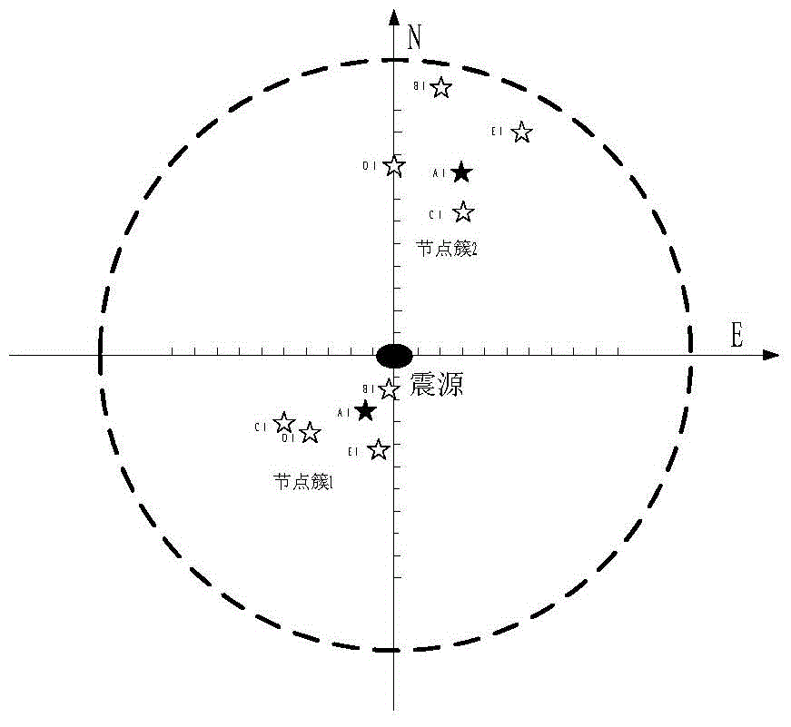
[0043] The distributed group wave shallow microseismic location method based on phase measurement goes through five steps of laying out the vibration sensor, extracting the phase information of the vibration signal, correcting the phase information, node cluster location and node group location, and finally realizes the distributed group wave shallow...


PUM


Abstract

The invention discloses a distributed group wave shallow-layer slight shock positioning method based on phase measuring. A distributed epicenter test system is employed, and the positioning of a distributed group wave shallow-layer slight shock epicenter is finally realized through five steps, i.e., shock sensor laying, shock signal phase information extraction, phase information calibration, node cluster positioning and node group positioning. According to the invention, sub-region node cluster laying and large-range node group random laying modes are adopted, a particle swarm algorithm is utilized for performing self-adaptive positioning on phase information corresponding to various advantaged frequency components, and a major constituent analytical method is utilized for data fusion of a positioning result so that the method provided by the invention has the advantages of low sensor laying difficulty, wide application scope, high positioning precision and reliability and the like.

Description

technical field [0001] The invention belongs to the field of blasting vibration testing technology and passive positioning technology, and in particular relates to a positioning method of a shallow underground microseismic source in a small area. Background technique [0002] Distributed underground seismic source positioning technology is to use the global positioning system (GPS) second pulse of each node to achieve synchronization between nodes in a small area that monitors shallow underground vibrations, and to pick up microseismic sources through each detection node after the earthquake. Vibration signal, use the storage acquisition module of the ground control system to realize data storage. When the underground microseismic process is over, the ground data forwarding system sends the data of each node to the central processing platform, and through the microseismic positioning algorithm, the source location is realized. [0003] Compared with large-area, large-equiva...

Claims


Application Information

Patent Timeline
Patent Type & Authority Applications(China)
IPC IPC(8): G01V1/00G01V1/20G01V1/30
Inventor 李剑姚金杰韩焱张丕状王黎明苏新彦刘琪芳潘烨炀刘莹石雅榕郭勇
Owner ZHONGBEI UNIV
Why Eureka
Try Eureka