Laser device plant light and manufacturing method thereof

A laser and lighting technology, applied in the fields of botanical equipment and methods, lighting and heating equipment, horticultural methods, etc., can solve the problems of high technical difficulty in the processing process, unsuitable for mass production, and difficult to meet the lighting requirements, and achieve the response time. The effect of short, high reliability, strong durability

Active Publication Date: 2014-03-12
Shandong Huaguang Optoelectronics Co. Ltd.
View PDF5 Cites 9 Cited by
  • Summary
  • Abstract
  • Description
  • Claims
  • Application Information

AI Technical Summary

Problems solved by technology

The processing technology of this patent is difficult, the structure is complex, and the production cost is high. It is not suitable for mass production, and it is even more difficult to meet the requirements of low cost and long life of plants.

Method used


Image

  • Laser device plant light and manufacturing method thereof
  • Laser device plant light and manufacturing method thereof

Examples


Embodiment 1

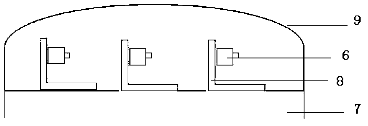
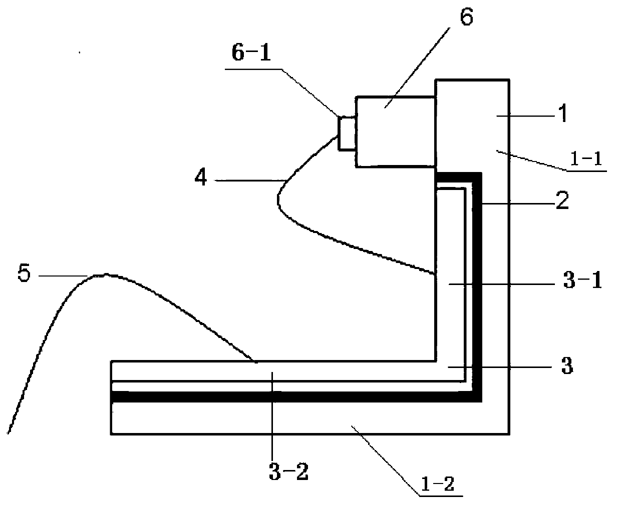
[0034] A laser plant lighting lamp, comprising a circuit board 7, a semiconductor laser die is packaged on the circuit board 7, and a dodging sheet 9 adapted to the shape of the circuit board 7 is covered above the semiconductor laser die The semiconductor laser tube core is an edge-emitting laser 6, and the semiconductor laser is electrically connected to the circuit board 7 through an L-shaped heat sink 8, and the L-shaped heat sink 8 includes an L-shaped negative electrode layer 1 , an L-shaped insulating layer 2 and an L-shaped positive electrode layer 3, an L-shaped groove is arranged on the inner surface of the L-shaped negative electrode layer 1, and the L-shaped positive electrode layer 3 is embedded in the described In the L-shaped groove, an L-shaped insulating layer 2 is arranged between the L-shaped negative electrode layer 1 and the L-shaped positive electrode layer 3; the semiconductor laser die is installed on the inner surface of the L-shaped negative electrode ...

Embodiment 2

[0039] A laser plant lighting lamp as described in Embodiment 1, the difference is that the material of the L-shaped negative electrode layer 1 is single crystal silicon. The L-shaped anode layer 3 is made of monocrystalline silicon.

[0040] The material of the L-shaped insulating layer 2 is silicone grease. The silicone grease described is DX-9041 thermal conductive silicone grease, commonly known as heat dissipation paste, which has good thermal conductivity, temperature resistance, and insulation properties. It is an ideal dielectric material for heat-resistant devices, and its performance is stable, and it will not produce Corrosive gases that do not affect the metals they come in contact with.

Embodiment 3

[0042] A laser plant lighting lamp as described in Example 1, the difference is that the material of the L-shaped insulating layer is an insulating and heat-conducting adhesive, and the insulating and heat-conducting adhesive is a type of one-component room temperature vulcanized silicone adhesive. It has the characteristics of convenient use, high bonding strength, elastic body after curing, impact resistance, vibration, etc. At the same time, the cured product also has good heat conduction, heat dissipation functions, excellent high and low temperature resistance and electrical properties.


PUM


Abstract

The invention discloses a laser device plant light. The laser device plant light comprises a circuit board. A semiconductor laser device pipe core is packaged on the circuit board, and a light uniformizing piece which is matched with the circuit board in shape covers the semiconductor laser device pipe core. The semiconductor laser device pipe core is an edge emitting type laser device, and a semiconductor laser device is electrically connected with the circuit board through an L-shaped heat sink. The L-shaped heat sink comprises an L-shaped negative electrode layer, an L-shaped insulating layer and an L-shaped positive electrode layer. An L-shaped groove is formed in the inner surface of the L-shaped negative electrode layer. The L-shaped positive electrode layer is embedded into the L-shaped groove. The L-shaped insulating layer is arranged between the L-shaped negative electrode layer and the L-shaped positive electrode layer. The laser device plant light can provide light rays with the wave length required by plants, and the laser device plant light has the obvious advantages of being good in spectrum performance, high in power, short in response time, small in size, high in reliability and durability, low in cost, long in service life, environmentally friendly, capable of saving energy and the like.

Description

technical field [0001] The invention relates to a laser plant lighting lamp and a preparation method thereof, belonging to the technical field of plant lighting lamps. Background technique [0002] Light is one of the basic factors for plant growth and development. Light quality has regulatory effects on plant growth, morphogenesis, photosynthesis, material metabolism and gene expression. As the fourth-generation new lighting source, LED lighting has many important characteristics different from other electric light sources, such as energy saving and environmental protection, safety and reliability, small size, light weight, easy to disperse or combine control, etc. With the explosive growth of plant factories, the market for plant lighting will further expand, and the main reasons for the increase in the number of plant factories are as follows: 1. China's urban population has increased sharply, and the number of farmers has continued to decrease, while plant factories hav...

Claims


Application Information

Patent Timeline
Patent Type & Authority Applications(China)
IPC IPC(8): F21S8/00F21V19/00F21V17/00A01G7/06A01G9/20
Inventor 夏伟张秋霞左致远于军陈康
Owner Shandong Huaguang Optoelectronics Co. Ltd.
Why Eureka
Try Eureka