Grooved Schottky device structure and manufacturing method thereof

A technology of device structure and manufacturing method, which is applied in the direction of semiconductor/solid-state device manufacturing, semiconductor devices, electrical components, etc., can solve the problems of reducing forward conduction voltage drop, inability to effectively control Schottky reverse leakage, etc., to reduce defects , a wide range of effects

Active Publication Date: 2014-03-12
CHINA RESOURCES MICROELECTRONICS (CHONGQING) CO LTD
View PDF3 Cites 13 Cited by
  • Summary
  • Abstract
  • Description
  • Claims
  • Application Information

AI Technical Summary

Problems solved by technology

[0008] In view of the shortcomings of the prior art described above, the purpose of the present invention is to provide a trench type Schottky device structure and a manufacturing method thereof,

Method used


Image

  • Grooved Schottky device structure and manufacturing method thereof
  • Grooved Schottky device structure and manufacturing method thereof
  • Grooved Schottky device structure and manufacturing method thereof

Examples


Embodiment Construction

[0051] Embodiments of the present invention are described below through specific examples, and those skilled in the art can easily understand other advantages and effects of the present invention from the content disclosed in this specification. The present invention can also be implemented or applied through other different specific implementation modes, and various modifications or changes can be made to the details in this specification based on different viewpoints and applications without departing from the spirit of the present invention.

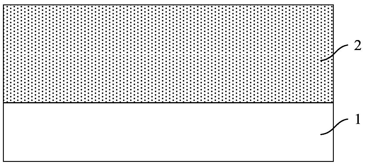
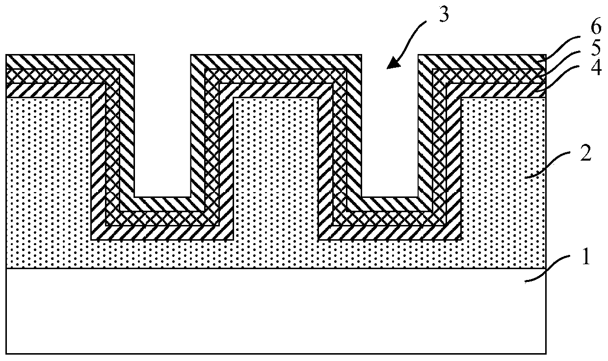
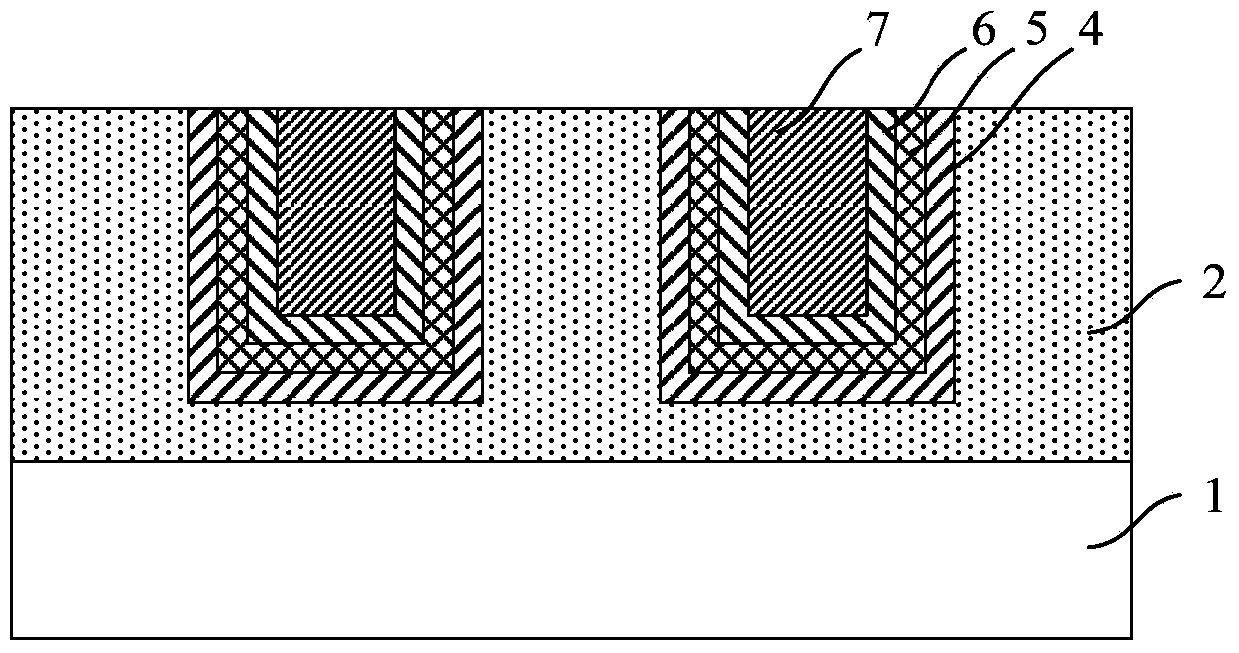
[0052] see Figure 1 to Figure 5 . It should be noted that the diagrams provided in this embodiment are only schematically illustrating the basic idea of ​​the present invention, and only the components related to the present invention are shown in the diagrams rather than the number, shape and shape of the components in actual implementation. Dimensional drawing, the type, quantity and proportion of each component can be changed arb...


PUM

PropertyMeasurementUnit
Thicknessaaaaaaaaaa
Thicknessaaaaaaaaaa
Width rangeaaaaaaaaaa

Abstract

The invention provides a grooved Schottky device structure and a manufacturing method thereof. The grooved Schottky device comprises an N-type heavily-doped substrate, an N-type lightly-doped silicon epitaxial layer, at least two grooves, N-type highly-doped polycrystalline silicon layers, a metal silicide layer, a positive electrode and a negative electrode, wherein the N-type heavily-doped silicon epitaxial layer is formed on the substrate; the grooves are formed in the silicon epitaxial layer; a first silicon dioxide layer, a middle medium layer and a second silicon dioxide layer are formed in sequence on the surface of each groove; the N-type highly-doped polycrystalline silicon layers are filled into the grooves; the metal silicide layer is formed on the surface of the silicon epitaxial layer; the positive electrode is formed on the surface of the metal silicide layer; the back electrode is formed on the back surface of the N-type heavily-doped substrate. According to the grooved Schottky device structure, a first silicon dioxide layer/middle medium layer/second silicon dioxide layer compound structure is taken as a groove medium layer, so that the leakage current can be reduced remarkably, the requirement on the increase of the breakdown voltage and the reduction of the leakage current are met, a narrow groove structure can be adopted, the Schottky potential barrier contact area is increased, and the positive break-over voltage is lowered.

Description

technical field [0001] The invention belongs to the field of semiconductors, and relates to a groove type Schottky device structure and a manufacturing method thereof. Background technique [0002] The power Schottky device is a semiconductor two-terminal device used for large current rectification. The commonly used power Schottky device is made of the Schottky junction between metal silicide and low-doped N-type silicon. Metal silicide The compound can be platinum-silicon compound, titanium-silicon compound, nickel-silicon compound and chromium-silicon compound, etc. In recent years, due to the development of trench technology, various trench structures have been used to make the leakage protection ring of the cell Schottky structure, such as the commonly used trench MOS structure. The adoption of the trench type MOS structure reduces the area of ​​the traditional PN junction protection ring, and when the chip area used by the device is the same, the forward conduction vo...

Claims


Application Information

Patent Timeline
IPC IPC(8): H01L21/329H01L29/872H01L29/06H01L29/40
CPCH01L29/0611H01L29/66143H01L29/872
Inventor 郑晨炎张小辛傅静
Owner CHINA RESOURCES MICROELECTRONICS (CHONGQING) CO LTD
Why Eureka
Try Eureka