Eureka AIR delivers breakthrough ideas for toughest innovation challenges, trusted by R&D personnel around the world.

Preposed denitrification aeration biofilter and method for treating sewage

A biological aerated filter and pre-denitrification technology, applied in biological water/sewage treatment, chemical instruments and methods, water/sludge/sewage treatment, etc., can solve the problem of increased operating costs, low treatment efficiency, and low cost and other issues to achieve the effect of increasing the contact time and area

Inactive Publication Date: 2014-03-19
NANJING UNIV
View PDF9 Cites 5 Cited by
  • Summary
  • Abstract
  • Description
  • Claims
  • Application Information

AI Technical Summary

Problems solved by technology

[0007] Aiming at the problems in the prior art that a large amount of additional oxygen supply is required to ensure a strict aerobic environment for nitrifying bacteria in the CN tank, the treatment efficiency is low, and the operating cost is increased, a pre-denitrification aerated biological filter and its treatment are provided. The sewage method can increase the dissolved oxygen in the CN tank, thereby reducing the subsequent pre-denitrification aerated biological filter with additional oxygen supply, and at the same time, the treatment efficiency is higher and the cost is lower

Method used


Image

  • Preposed denitrification aeration biofilter and method for treating sewage

Examples


Embodiment 1

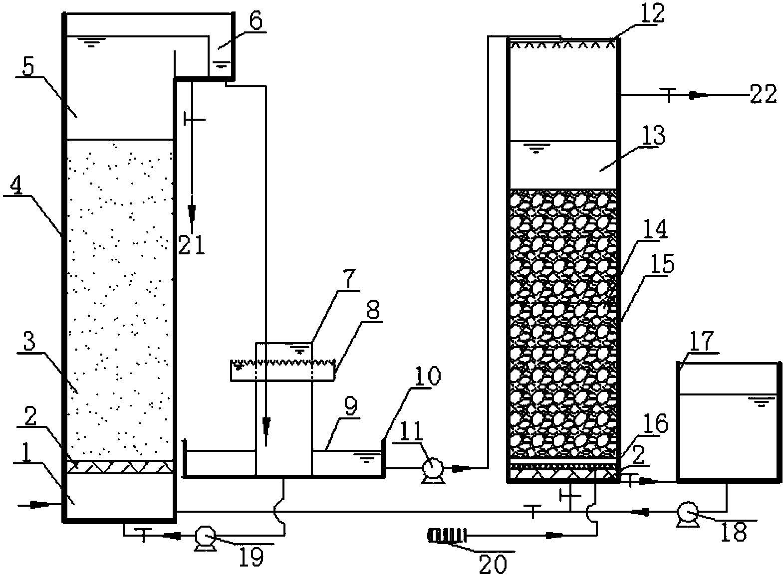
[0035] Such as figure 1 As shown, a pre-denitrification biological aerated filter includes a DN pool body 4 and a CN pool body 15, and also includes a first water storage tank body 10, a second water storage tank body 17 and an aeration pump 20; the DN pool body 4. The interior includes clean water area 5, sea sand filter material layer 3, supporting layer 2 and water distribution buffer zone 1 from top to bottom; water inlet is provided on one side of water distribution buffer zone 1; The water tank 6, the water outlet tank 6 and the clean water area 5 are separated by a water baffle, and the height of the water baffle is lower than the height of the top of the DN pool body 4; one side of the clean water area 5 is also provided with a DN pool backwash drain pipe 21 ; The middle part of the first water storage tank body 10 is placed with a first water storage tank inner cylinder 7; the outer side of the first water storage tank inner cylinder 7 is provided with an annular wate...

Embodiment 2

[0047] Same as Example 1, the difference is that the sea sand filter material layer 3 has a thickness of 1.5m; the zeolite packing layer 14 has a thickness of 1.6m.

Embodiment 3

[0049] Same as Example 1, the difference is that the sea sand filter material layer 3 has a thickness of 1.7m; the zeolite packing layer 14 has a thickness of 1.4m.


PUM

PropertyMeasurementUnit
particle diameteraaaaaaaaaa
densityaaaaaaaaaa
specific surface areaaaaaaaaaaa

Abstract

The invention discloses a preposed denitrification aeration biofilter and a method for treating sewage and belongs to the field of wastewater treatments. The biofilter comprises a DN tank body and a CN tank body and further comprises a first water storage tank body, a second water storage tank body and an aeration pump, wherein a first water storage tank inner cylinder is placed in the middle of the first water storage tank body; an annular water storage tank buffering groove is arranged at the outer side of the first water storage tank inner cylinder; the height of the water storage tank buffering groove is lower than that of the first water storge tank inner cylinder; and the area between the side wall of the first water storage tank body and the first water storge tank inner cylinder is a first water storage tank storage area. As the water flowing direction of the DN tank is upward, suspended solids are prevented from concentrating in a filler layer, the dirt containing rate of a filler is increased, and backwashing interval time is prolonged. By adopting the preposed denitrification aeration biofilter, the dissolved oxygen of the feeding water of the CN tank can be improved without power, so that subsequent additional oxygen supply amount is reduced; and the preposed denitrification aeration biofilter has the advantages of simple structure, convenient operation and low energy consumption.

Description

technical field [0001] The invention belongs to the field of waste water treatment, in particular, relates to a pre-denitrification biological aerated filter and its method for treating sewage, more specifically, relates to a pre-stage denitrification biological aerated filter for sewage treatment containing organic matter and ammonia nitrogen Denitrification aerated biological filter and its method for treating sewage. Background technique [0002] Due to its small footprint, low maintenance cost, easy operation, convenient and flexible operation and management, the biological filtration system has been widely used in sewage denitrification treatment. Although the single upward flow biological aerated filter has a high removal rate of ammonia nitrogen, the removal rate of total nitrogen is very low. In order to increase the removal rate of total nitrogen, a combination of multiple filters in parallel is often used for nitrification and denitrification denitrification. The...

Claims


Application Information

Patent Timeline
Patent Type & Authority Applications(China)
IPC IPC(8): C02F3/30C02F3/34
Inventor 任洪强胡海冬周莉娜丁原红高映海
Owner NANJING UNIV
Why Eureka
Eureka Blog
Learn More