
A Low-Energy Two-Phase CO2 Capture Method

A technology of CO2 and low energy consumption, which is applied in the field of two-phase capture of CO2 with low energy consumption, can solve the problems of high energy consumption of calcium carbonate regeneration, in the ascendant of research and development, and low absorption capacity, and achieve fast absorption/desorption speed, excellent thermal stability and Chemical stability and large absorption capacity

Active Publication Date: 2015-10-28
ZHEJIANG UNIV
View PDF1 Cites 0 Cited by
  • Summary
  • Abstract
  • Description
  • Claims
  • Application Information

AI Technical Summary

Problems solved by technology

However, since Ca(OH) 2 Solubility in water is very small, lime water has little effect on CO 2 The absorption capacity of calcium carbonate is low; and the regeneration energy consumption of high temperature calcined calcium carbonate is very high (179.2kJ / mol CO 2 ), so the application of this two-phase capture method is severely restricted, limewater in CO 2 Little practical application in capturing
[0005]Because of the above-mentioned shortcomings in existing capture technologies and methods, the development of new and efficient CO2 capture methods is in the ascendant in recent years

Method used


Image

  • A Low-Energy Two-Phase CO2 Capture Method
  • A Low-Energy Two-Phase CO2 Capture Method
  • A Low-Energy Two-Phase CO2 Capture Method

Examples


Embodiment 1~7

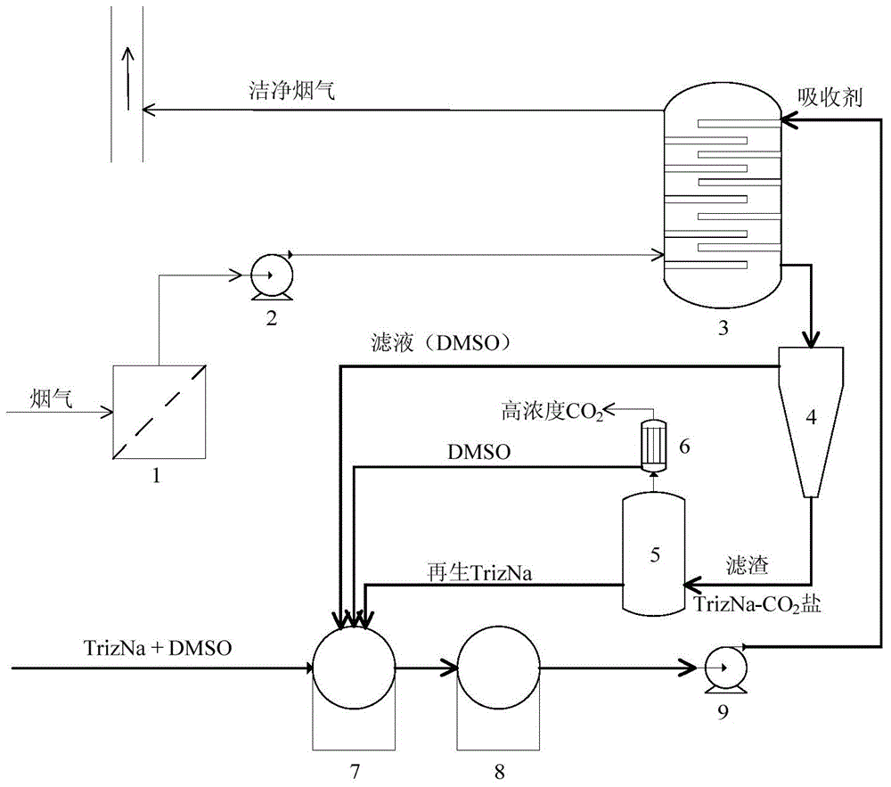
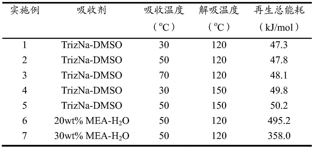
[0029] For CO in TrizNa-DMSO solution system 2 The total regeneration energy consumption of the absorption-desorption process is tested, the absorption condition is 30°C, 1atm, the desorption condition is 120°C, 1atm, according to figure 1 The technological process is carried out, and the total regeneration energy consumption of the TrizNa-DMSO solution system is calculated to be 47.3kJ / molCO 2 .

[0030] The total energy consumption of regeneration consists of three parts: desorption reaction heat, solution evaporation heat and solution sensible heat:

[0031] (1) The absorbent solution absorbs CO 2TrizNa-CO 2 Salt, precipitated out, its desorption enthalpy is 29.7kJ / mol CO 2 , much lower than the desorption enthalpy of ethanolamine (~80.0 kJ / mol).

[0032] (2) TrizNa-CO 2 The DMSO content in the salt is 10wt%, assuming complete volatilization, the calculated heat of vaporization of DMSO is 9.8kJ / mol CO 2 .

[0033] (3) During regeneration, 1 g of TrizNa-CO after cent...

Embodiment 8~13

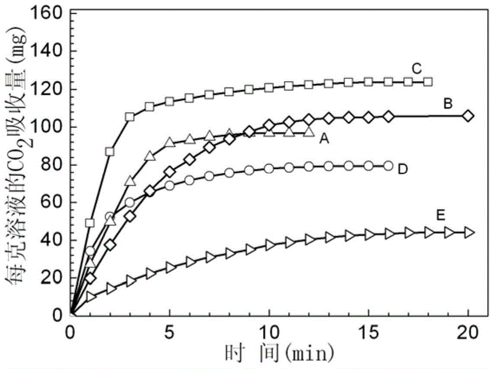
[0038] To the CO of 5wt% TrizNa-DMSO solution 2 The absorption capacity is tested, the absorption condition is 30°C, 1atm, pure CO 2 atmosphere, CO 2 The flow rate is 50ml / min. CO was measured after 5min 2 The absorption capacity is 27.3mg CO 2 / g solution.

[0039] Under the same test conditions, the CO of different concentrations of TrizNa-DMSO solutions 2 Absorption data are listed in Table 2.

[0040] Table 2

[0041]

Embodiment 14~17

[0043] For 10wt% TrizNa-H 2 CO in O solution system 2 The absorption capacity is tested, the absorption condition is 30°C, 1atm, pure CO 2 atmosphere, CO 2 The flow rate is 50ml / min. CO was measured after 25min 2 The absorption capacity is 37.1mg CO 2 / g solution.

[0044] Under the same test conditions, the CO of the TrizNa solution system (where the mass fraction of TrizNa is 10wt%) prepared by different solvents 2 Absorption data are listed in Table 3.

[0045] table 3

[0046]


PUM


Abstract

The invention discloses a low-energy two-phase CO2 capture method, comprising the following steps: (1) mixing a triazole metal salt with a solvent to prepare an absorbent, leading an exhaust gas containing CO2 to the absorbent, generating a product of fine grains by the triazole metal salt after absorbing the CO2, participating the product from a solution, so as to form a two-phase system; (2) separating the two-phase system obtained in the step (1), so as to obtain a sediment and filtrate, reusing the filtrate in the step (1); (3) carrying out heating regeneration treatment on the sediment obtained in the step (2), reusing the obtained triazole metal salt in the step (1), collecting CO2 after condensing the obtained gaseous phase, reusing the solvent generated by condensation in the step (1), wherein the mass percent of the absorbent is 10-40%. The CO2 capture and separation method has the advantages of being low in viscosity, fast in absorption / desorption speed, high in selectivity, large in absorption capacity, and especially low in regeneration energy consumption, and can be recycled.

Description

technical field [0001] The invention relates to acid gas absorption technology, in particular to a low energy consumption two-phase capture CO 2 Methods. Background technique [0002] In recent years, global warming, a climate crisis, has attracted more and more attention as a worldwide problem related to the living environment of all human beings. Since the industrial revolution, human production and life have been increasingly dependent on fossil raw materials. In current industrial production, fossil fuels provide 85% of the energy source. Due to the widespread use of fossil fuels, large amounts of CO 2 is emitted into the atmosphere, CO in the atmosphere 2 The concentration of carbon dioxide has increased from 270ppm before the industrial revolution to the current 390ppm, which is considered to be the main cause of the greenhouse effect. CO 2 Emission reduction and control has become one of the biggest technological challenges in the 21st century. Therefore, carbon...

Claims


Application Information

Patent Timeline
Patent Type & Authority Patents(China)
IPC IPC(8): B01D53/78B01D53/62B01D53/96
CPCY02C10/04Y02A50/20Y02C20/40
Inventor 吴林波任杰李伯耿
Owner ZHEJIANG UNIV
Learn More