
Manufacturing method of pressure head used on thermal force simulation testing machine

A technology of thermal simulation and manufacturing method, applied in the direction of metal processing equipment, etc., can solve the problems of complex manufacturing process, delayed production cycle, shortened service life, etc., to achieve the effect of reducing blank defects, reducing processing strength and prolonging service life

Active Publication Date: 2015-07-08
ANGANG STEEL CO LTD
View PDF11 Cites 0 Cited by
  • Summary
  • Abstract
  • Description
  • Claims
  • Application Information

AI Technical Summary

Problems solved by technology

Although this method can produce anvils with the above-mentioned properties, the alloy composition and content of the materials are strictly controlled, and the raw materials are all in powder state. The manufacturing process is relatively complicated and the production cycle is also long.
Whether it is the indenter or anvil manufactured by the above-mentioned die casting method or powder metallurgy method, there are disadvantages of high production cost and complicated production process.
In addition, the indenter or anvil produced by the existing technology is a single alloy structure, which is easy to stick to the simulated sample under high temperature or high temperature deformation conditions, which greatly shortens its service life and delays the production cycle

Method used


Image

  • Manufacturing method of pressure head used on thermal force simulation testing machine
  • Manufacturing method of pressure head used on thermal force simulation testing machine
  • Manufacturing method of pressure head used on thermal force simulation testing machine

Examples


Embodiment

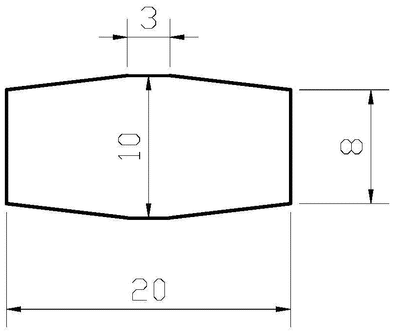
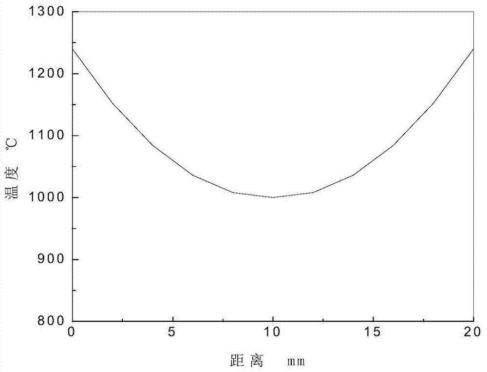
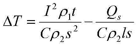
[0024] 1. The material of the blank is FeCrNi high-temperature high-strength steel. Process the blank for manufacturing the indenter into an olive shape with thin ends and a thick middle, and its cross-section is circular. The radius of the thin end is 4mm, and there is a thicker part with a length of 3mm in the middle. 20mm, specific shape and size such as figure 1 shown. This shape design makes the billet produce a certain temperature gradient in the subsequent electric heating process, and the specific temperature distribution formula is:

[0025] Q=I 2 Rt-Q s =CmΔT (1)

[0026] Among them: Q s is the heat loss, I is the current intensity passing through the billet, R is the resistance, t is the heating time, C is the specific heat, ΔT is the temperature value of the billet rising from room temperature;

[0027] If the resistivity of the blank is ρ 1 , the length is l, the cross-sectional area is s, and the density is ρ 2 , then it can be obtained from formula (1): ...


PUM


Abstract

The invention provides a manufacturing method of a pressure head used on a thermal force simulation testing machine. The manufacturing method of the pressure head used on the thermal force simulation testing machine includes: processing a blank into an olive shape with two ends fine and the middle thick, determining temperature when shrinking rate of a cross section of the blank is large or the maximum stress value of the cross section of the blank is low to be heating or deformation temperature of the blank, placing the blank between two anvil heads which both have heating and hot pressing deformation functions after a thermoelectric couple is welded on the thickest middle position of the olive-shaped blank, adding a spacer between the blank and each anvil head, and performing 2-7 times of compression deformation on the blank after the blank is heated to the deformation temperature through voltage applied between the two anvil heads so as to combine the spacers and the blank into a whole, wherein deformation amount in each time of the compression deformation is larger than deformation amount in the last time of the compression deformation. The manufacturing method of the pressure head used on the thermal force simulation testing machine can reduce deformation resistance when the blank is compressed, decreases the number of defects of the blank, improves strength of the pressure head, prolongs service life of the pressure head, avoids adhesion between the blank and each anvil head, simplifies processing technology, shortens the production cycle, and reduces manufacturing cost.

Description

technical field [0001] The invention belongs to the field of testing equipment, in particular to a method for manufacturing a high-strength indenter for a thermal simulation testing machine. Background technique [0002] The thermal simulation testing machine treats the simulated sample as a resistance and directly heats it with electricity. The indenter of the thermal simulation testing machine in contact with the simulated sample can be regarded as two heating electrodes, and the simulated sample is used as a heating resistor. Since the simulated sample is in direct contact with the indenter as a heating electrode, the indenter is also heated to a certain temperature while the sample is heated. Therefore, the indenter is required to have good electrical conductivity, high temperature strength, hardness, and oxidation resistance. At present, the material of the indenter of the thermal simulation testing machine is mostly made of alloy-based materials based on tungsten, suc...

Claims


Application Information

Patent Timeline
Patent Type & Authority Patents(China)
IPC IPC(8): B21J5/06B21J1/02B21J1/06
Inventor 赵宝纯李桂艳刘凤莲隋晓红赵坦黄磊李广龙王晓峰
Owner ANGANG STEEL CO LTD
Learn More