
Fuel-saving/gas-ignition stable-combustion low-nitrogen swirling pulverized coal combustor

A technology of pulverized coal burners and burners, which is applied in the direction of burners, burners, and combustion methods for burning powder fuels, and can solve the problem of low nitrogen and stable combustion performance of the entire row of swirl burners, and lack of low nitrogen combustion In order to achieve the effects of strong adaptability to coal types, wide practicability, and strong adaptability to coal types

Active Publication Date: 2014-04-30
XUZHOU KERONG ENVIRONMENTAL RESOURCES CO LTD +1
View PDF7 Cites 13 Cited by
  • Summary
  • Abstract
  • Description
  • Claims
  • Application Information

AI Technical Summary

Problems solved by technology

However, many low-nitrogen burners currently have problems such as severe wear, slagging at the nozzle and high-temperature corrosion, and are not well adaptable to coal types.
[0004] At present, as far as the swirl burners of wall-fired boilers are concerned, the application method of fuel-saving ignition technology is to remove the primary air part of a row of swirl burners and replace them with fuel-saving ignition pulverized coal burners, and fuel-saving ignition pulverized coal The burner does not have the performance structure of a low-nitrogen burner when the boiler is in normal operation, which often reduces the low-nitrogen and stable combustion performance of the entire row of swirl burners used for fuel-saving ignition technology

Method used


Image

  • Fuel-saving/gas-ignition stable-combustion low-nitrogen swirling pulverized coal combustor
  • Fuel-saving/gas-ignition stable-combustion low-nitrogen swirling pulverized coal combustor

Examples


Embodiment Construction

[0012] An embodiment of the present invention will be further described below in conjunction with accompanying drawing:

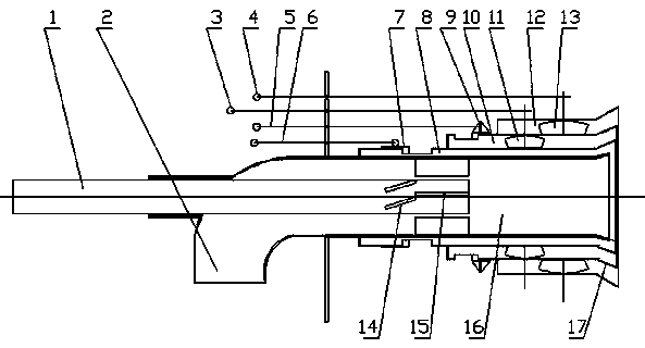
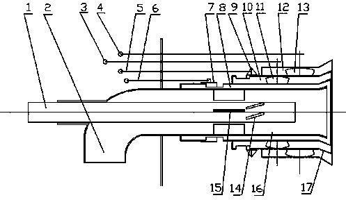
[0013] The fuel-saving / gas ignition and stable combustion low-nitrogen swirl pulverized coal burner of the present invention is mainly composed of an oil / gas burner 1, a primary air channel 2, a damper, an adjustment rod, a secondary air inlet pipe 8, and a secondary air flow in the swirl flow. The air inlet pipe 10, the secondary air inlet pipe 12 outside the swirl flow and the swirl flow blades are formed. The oil / gas burner 1 extends into the primary air channel 2, and the outer wall of the horizontal pipe section of the primary air channel 2 is provided with a guide sleeve that allows the oil / gas burner 1 to enter the primary air channel 2 and move back and forth. The axis line of the gas burner 1 coincides with the axis line of the horizontal pipe section of the primary air channel 2 . The outlet ends of the primary air channel 2, the secondary ai...


PUM


Abstract

A fuel-saving / gas-ignition stable-combustion low-nitrogen swirling pulverized coal combustor comprises a primary air channel, a multi-channel secondary air intake tube and a fuel / gas combustor. A circle of rectifying vanes are evenly distributed on the inner wall of an entryway of a strengthening combustion chamber in the primary air channel, a circle of swirling vanes are evenly distributed on the front outer wall of the fuel / gas combustor, the length from front the end of each swirling vane to the front end of the fuel / gas combustor is larger then or equal to the length of each overall rectifying vane, and the outer diameter of each swirling vane is smaller than the inner diameter of each rectifying vane; the fuel / gas combustor is back-front adjustable and capable of driving relative positions between the swirling vanes and the rectifying vanes to change; swirling intensity of secondary air of the combustor can be adjusted online, a reasonable high-temperature flue gas recirculation zone is formed in a nozzle center of the combustor through adjustment of the swirling intensity of the secondary air, and stable heat sources are provided for ignition and stable combustion of pulverized coal; timely mixing of the secondary air and the pulverized coal is effectively controlled, and a water-cooled wall area at the position of a nozzle is enabled to be in the oxidizing atmosphere, so that scorification and high-temperature corrosion of a water-cooled wall in the area of the combustor can be effectively prevented.

Description

technical field [0001] The invention relates to a pulverized coal burner, in particular to a pulverized coal burner suitable for power plant boilers which is fuel-saving / gas-ignited, stable-combustible, and low-nitrogen swirling flow. Background technique [0002] At present, pulverized coal boilers in power stations in the world generally use large oil guns to achieve start-up and low-load stable combustion. According to statistics, the domestic power system uses nearly 10 million tons of oil for boiler commissioning, start-up, low-load stable combustion, and shutdown for combustion-supporting fuel, accounting for 15% of the country's total fuel consumption, worth tens of billions of yuan, and consuming a large amount of oil. fuel resources, but also greatly increase the cost of power generation. China's coal resources are much more abundant than oil and gas resources, and the energy consumption structure dominated by coal has not changed in recent decades. The power gene...

Claims


Application Information

Patent Timeline
Patent Type & Authority Applications(China)
IPC IPC(8): F23D1/02
CPCF23D1/02F23C2900/06041F23D1/00F23D2201/10F23D2201/20
Inventor 高克迎程怀志
Owner XUZHOU KERONG ENVIRONMENTAL RESOURCES CO LTD
Learn More