Method for manufacturing micro-polarizer array based on metal nanometer grating

A technology of micro polarizer array and manufacturing method, which is applied in the direction of polarizing element, photographic plate-making process of pattern surface, optics, etc., can solve the problems of poor shape of polarizer array, poor polarization performance, complicated process, etc., and achieve high extinction Ratio, good straight wall, high resolution effect

Active Publication Date: 2014-04-30
THE NAT CENT FOR NANOSCI & TECH NCNST OF CHINA
View PDF9 Cites 30 Cited by
  • Summary
  • Abstract
  • Description
  • Claims
  • Application Information

AI Technical Summary

Problems solved by technology

The method is suitable for making gratings in a single direction, and the efficiency is low
[0005] In 2011, Viktor Gruev et al. (Optics Express, 19, P24361, 2011) proposed to use the laser interference multiple ex

Method used


Image

  • Method for manufacturing micro-polarizer array based on metal nanometer grating
  • Method for manufacturing micro-polarizer array based on metal nanometer grating
  • Method for manufacturing micro-polarizer array based on metal nanometer grating

Examples


Embodiment 1

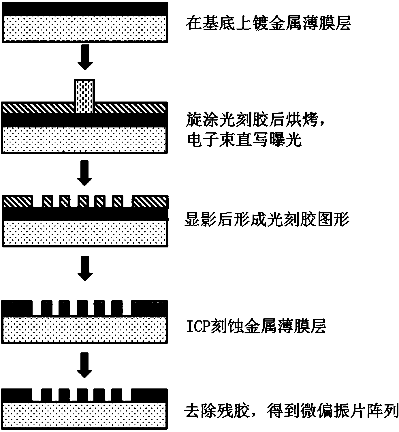
[0034] according to figure 2 As shown in the process flow, the method for preparing a micro-polarizer array based on a metal nano-grating by using a single electron beam exposure provided in this embodiment includes the following steps:

[0035] Step 1: Deposit a thin film layer of metallic aluminum (Al) on a glass substrate.

[0036] In this step, a 100nm-thick metal Al thin film layer is deposited on the cleaned glass substrate by using magnetron sputtering technology. According to the extinction requirement, the thickness of the Al thin film layer can be any value between 100-150 nm.

[0037] Step 2: Spin-coat the electron beam photoresist on the glass substrate with the metal Al film layer, and form the electron beam photoresist pattern of the micropolarizer array after exposure and development. The specific process is as follows:

[0038]a. Place the glass substrate with metal Al thin film layer on a hot plate and bake at 180°C for 5-10 minutes to remove the moisture o...

Embodiment 2

[0047] according to figure 2 As shown in the process flow, the method for preparing a micro-polarizer array based on a metal nano-grating by using a single electron beam exposure provided in this embodiment includes the following steps:

[0048] Step 1: Deposit a metal chromium (Cr) film layer on a glass substrate.

[0049] In this step, electron beam evaporation technology is used to deposit a 120 nm thick metal Cr thin film layer on the cleaned glass substrate. According to the extinction requirement, the thickness of the Cr thin film layer can be any value between 100-150 nm.

[0050] Step 2: Spin-coat the electron beam photoresist on the glass substrate with the metal Cr film layer, and form the electron beam photoresist pattern of the micropolarizer array after exposure and development. The specific process is as follows:

[0051] a. Place the glass substrate with the metal Cr film layer on a hot plate and bake at 150°C for 5-10 minutes to remove the moisture on the su...

Embodiment 3

[0060] according to figure 2 As shown in the process flow, the method for preparing a micro-polarizer array based on a metal nano-grating by using a single electron beam exposure provided in this embodiment includes the following steps:

[0061] Step 1: Deposit a metal (Al) thin film layer on a glass substrate.

[0062] In this step, an electron beam evaporation technique is used to deposit a 100 nm-thick metal Al thin film layer on the cleaned glass substrate. According to the extinction requirement, the thickness of the Al thin film layer can be any value between 100-150 nm.

[0063] Step 2: Spin-coat the electron beam photoresist on the glass substrate with the metal Al film layer, and form the electron beam photoresist pattern of the micropolarizer array after exposure and development. The specific process is as follows:

[0064] a. Place the glass substrate with metal Al film layer in an oven and bake at 170°C for 40 minutes to remove the moisture on the surface, spin-...


PUM

PropertyMeasurementUnit
Thicknessaaaaaaaaaa
Thicknessaaaaaaaaaa

Abstract

The invention relates to a method for manufacturing a micro-polarizer array based on a metal nanometer grating. The method comprises the steps that (1) a substrate is coated with a metal film layer, and the metal film layer is dried; (2) the metal film layer is coated with an electron beam positive photoresist layer in a spinning mode, and the electron beam positive photoresist layer is dried; (3) electron beam direct writing, exposure and developing are conducted on the photoresist layer, and then a photoresist nanoscale micro-polarizer array graph is obtained; (4) inductive coupled plasma is used for etching, wherein the photoresist layer with the image is used as a mask, the metal film layer is etched, and therefore the image is transferred to the metal film layer; (5) the photoresist layer is removed, and then the micro-polarizer array is obtained. The method for manufacturing the micro-polarizer array based on the metal nanometer grating is easy to implement. According to the method for manufacturing the micro-polarizer array based on the metal nanometer grating, the micro-polarizer array with multiple different polarization directions can be obtained through one-time exposure and developing; the polarization performance of the micro-polarizer array manufactured according to the method is high.

Description

technical field [0001] The invention relates to the technical field of manufacturing diffractive optical elements, in particular to a method for manufacturing a micro-polarizer array based on a metal nano-grating. Background technique [0002] The micro-polarizer array is a device used to measure the light intensity of each polarization direction after the light passes through the polarizers in different directions. An image sensor (such as a digital camera) is used to collect images containing each polarization component obtained by the micro-polarizer array. images, and can perform real-time phase shift analysis. The micropolarizer array has wide application potential in the fields of real-time phase shifting of interference light, weak visible light image enhancement, and infrared target recognition. [0003] In the Chinese invention patent application CN103048268A, Zhang Qingchuan and others proposed a digital electronic shearing speckle interferometer based on a microp...

Claims


Application Information

Patent Timeline
IPC IPC(8): G02B27/28G02B5/30G03F7/00
Inventor 董凤良徐丽华苗霈宋志伟闫兰琴褚卫国
Owner THE NAT CENT FOR NANOSCI & TECH NCNST OF CHINA
Why Eureka
Try Eureka