Device and method for automatic, static continuous preparation of fiber bragg grating array

A technology of fiber grating array and fiber grating, which is applied in cladding optical fiber, optical waveguide light guide, etc., can solve the problems of low production cost and high mechanical strength of fiber grating array, and achieve high mechanical strength, simple operation and easy realization, good consistency

Inactive Publication Date: 2014-05-07
WUHAN UNIV OF TECH +1
View PDF5 Cites 22 Cited by
  • Summary
  • Abstract
  • Description
  • Claims
  • Application Information

AI Technical Summary

Problems solved by technology

[0004] The technical problem to be solved by the present invention is to provide a device and method for automatically and statically and continuously preparing fiber grating arrays, which can overcome the above-mentioned problems in the preparation of existing fiber grating arrays, and can prepare fiber gratings for ordinary single-mode fibers that do not carry hydrogen Array, its reflectivity can be customized according to needs, the distance between adjacent fiber gratings can be controlled arbitrarily, and it can be mass-produced, its production cost is low, and the finished fiber grating array has high mechanical strength

Method used


Image

  • Device and method for automatic, static continuous preparation of fiber bragg grating array
  • Device and method for automatic, static continuous preparation of fiber bragg grating array
  • Device and method for automatic, static continuous preparation of fiber bragg grating array

Examples


Embodiment Construction

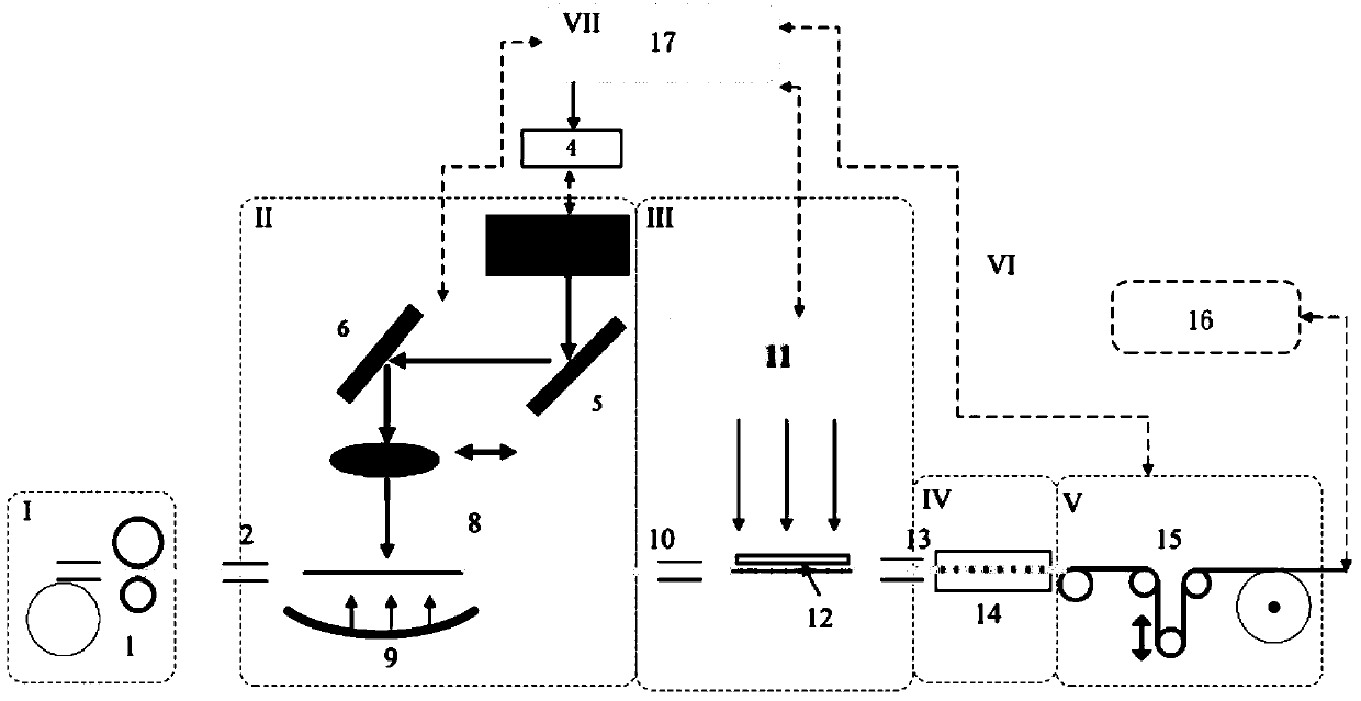
[0036] Specific embodiments of the present invention are described in further detail below in conjunction with the accompanying drawings:

[0037] like figure 1 As shown, a device of the present invention for automatically and continuously preparing a fiber grating array comprises an optical fiber pay-off module I, a coating layer stripping module II, a grating writing module III, a coating module IV and Fiber collection module V, in addition, in order to facilitate the process monitoring of some modules and the automatic control of the whole device, there is also a fiber grating array online monitoring module VI and a computer control module VII. In the optical fiber pay-off module I, the coating layer stripping module II and the grating writing module III, there are optical fiber clamps between the two adjacent modules for the support and temporary fixation of the optical fiber, so as to realize the operation performed by each module. In the embodiment, the optical fiber el...


PUM


Abstract

A device for automatic, static continuous preparation of a fiber bragg grating array comprises an optical fiber paying-off module, a coating layer stripping module, an optical grating inscribing module, a coating module and a fiber winding module, wherein the optical fiber paying-off module, the coating layer stripping module, the optical grating inscribing module, the coating module and the fiber winding module are sequentially arranged in the optical fiber running direction. The optical fiber paying-off module comprises a coiling drum. The coating layer stripping module comprises a CO2 pulse laser, a first reflector, a second reflector, a focusing lens and a cylindrical surface reflector arranged in sequence. The optical grating inscribing module comprises an excimer laser and a phase mask plate. The coating module comprises an automatic ultraviolet light coating device. The fiber winding module comprises an automatic fiber winding device. A method for automatic, static continuous preparation of the fiber bragg grating array aims at non-hydrogen-loaded common fibers, and in the optical fiber paying-off and winding process, the method includes the first step of partially stripping coating layers of fibers through narrow-pulse infrared light, the second step of moving optical fiber portions of the stripped coating layers to the excimer laser for inscribing, the third step of moving the optical fiber portions after being inscribed to the ultraviolet light coating device for ultraviolet light coating and curing, and the fourth step of repeating the first step to the third step to carry out inscribing on multiple fiber bragg gratings to form the fiber bragg grating array.

Description

technical field [0001] The invention relates to the preparation of fiber grating arrays in optical fiber sensing systems, in particular to a device and method for automatically and statically preparing fiber grating arrays continuously. Background technique [0002] At present, the multiplexing technology of quasi-distributed fiber Bragg grating is derived from its own high-sensitivity sensing function for external physical quantities such as temperature, stress, pressure and vibration. Due to its high performance and outstanding advantages, it has become the most powerful competitor in the field of optical fiber sensing, and has a wide range of applications in many industrial and engineering fields, especially in ultra-large structures. [0003] In the traditional grating multiplexing sensing system, most of them adopt the wavelength division multiplexing method of fusion welding of a single high-reflection non-uniform grating unit. The number of reuse is limited, generall...

Claims


Application Information

Patent Timeline
Patent Type & Authority Applications(China)
IPC IPC(8): G02B6/02
Inventor 唐健冠郭会勇程乘余海湖何伟姜德生陈宏利
Owner WUHAN UNIV OF TECH
Why Eureka
Try Eureka