
Current control method for three-phase voltage source type PWM rectifier
A three-phase voltage and current control technology, applied in the direction of converting AC power input to DC power output, electrical components, output power conversion devices, etc., can solve the problems of unstable rectifier operation, inability to guarantee controllers, and reducing the number of sensors. , to achieve good robust stability, no reduction of filtering effect, and good control effect.
- Summary
- Abstract
- Description
- Claims
- Application Information
AI Technical Summary
Problems solved by technology
Method used
Image

Examples
Embodiment Construction
[0030] The present invention will be further described below in conjunction with the accompanying drawings and specific embodiments.
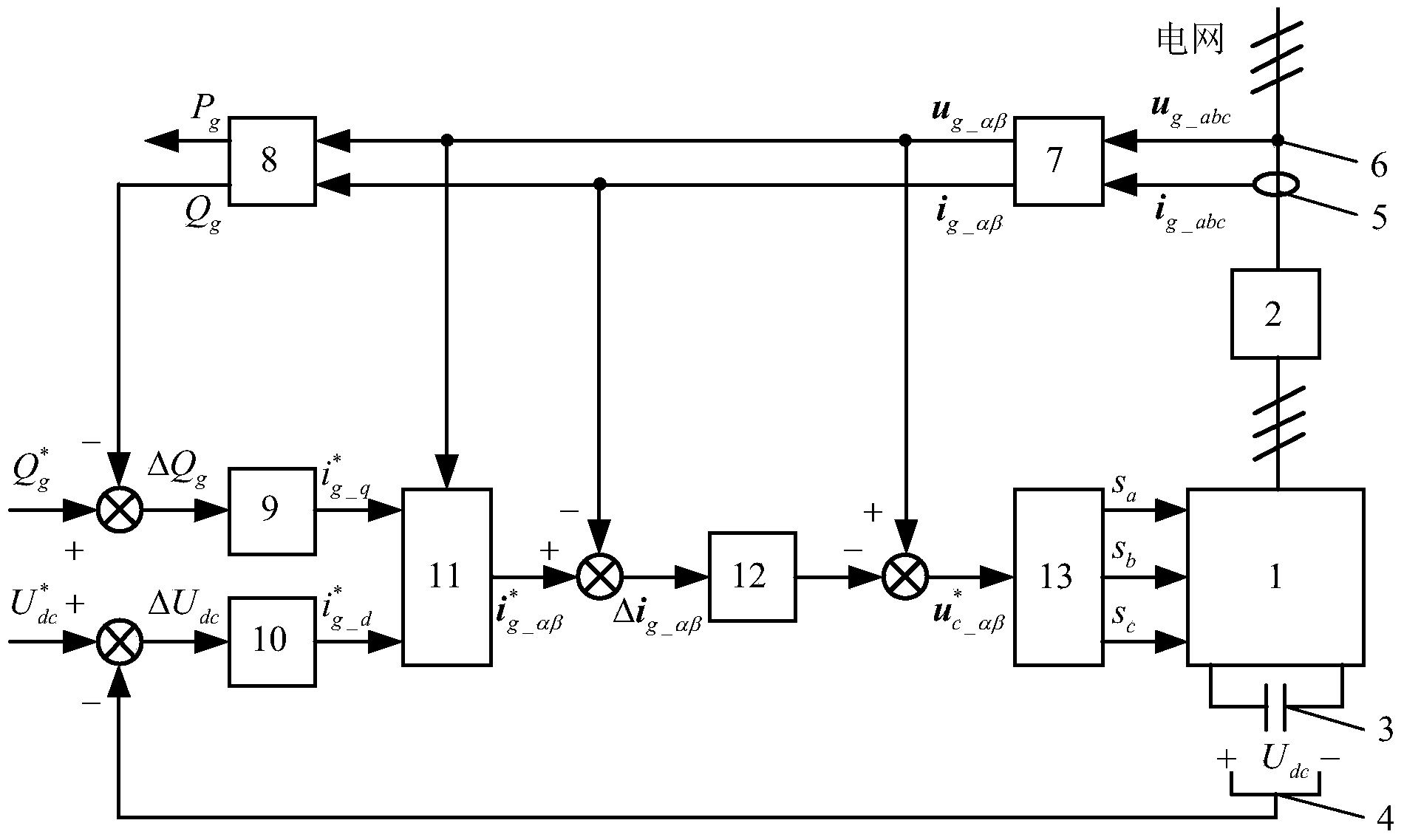
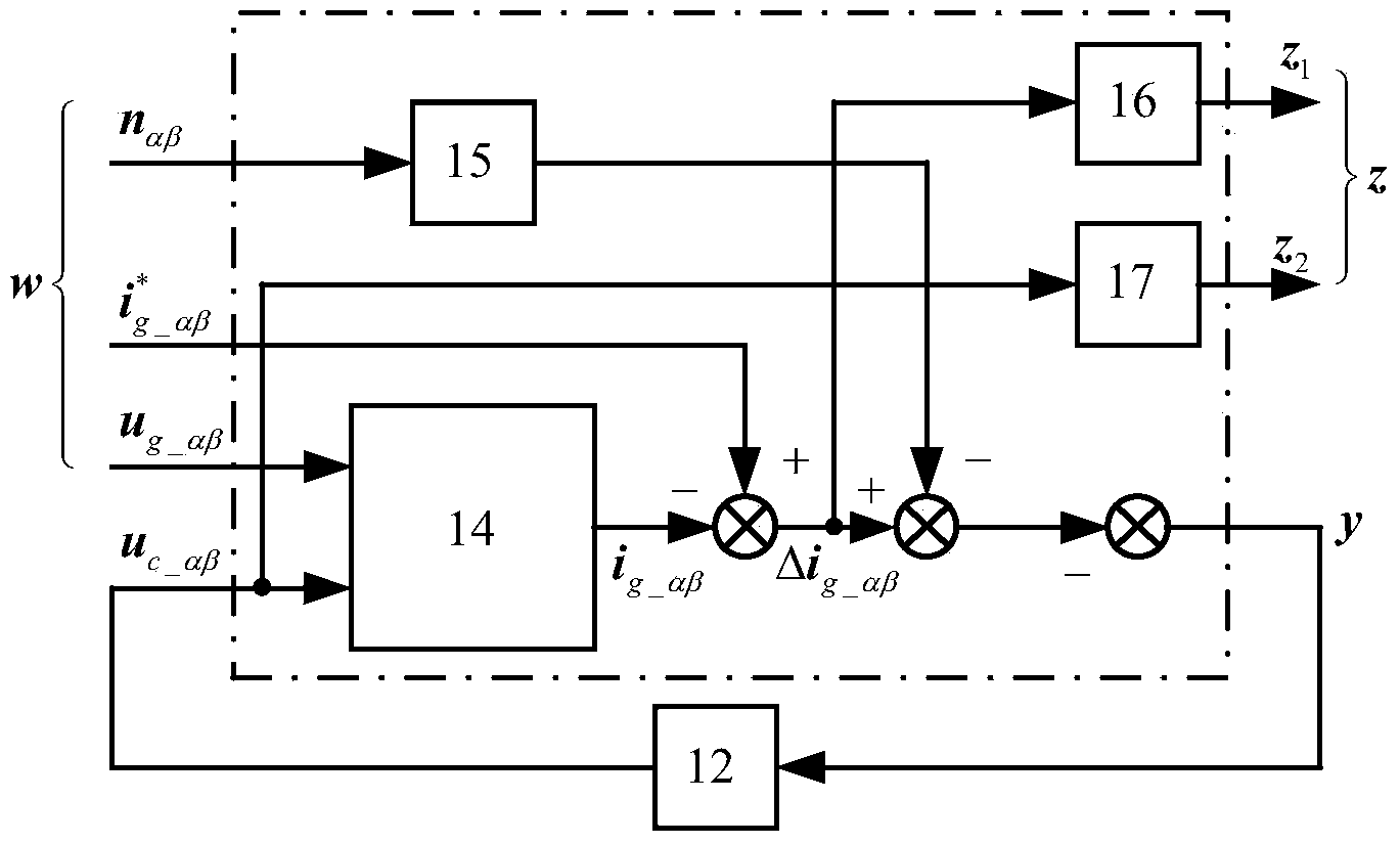
[0031] The present invention provides a current control method for a three-phase voltage source type PWM rectifier, which adopts a double-closed-loop vector control strategy in a static coordinate system. The design problem of the inner loop H∞ current regulator is transformed into solving an H∞ optimal problem, that is, firstly design a reasonable control object and weight function model, and then use the H∞ problem iterative algorithm to solve the required parameterized H ∞ Current Regulator.
[0032] figure 1 It is a vector control schematic diagram of a three-phase voltage source rectifier of the present invention, which includes a rectifier bridge 1, an LCL filter 2, a DC bus capacitor 3, a DC voltage sensor 4, a three-phase AC current sensor 5, a three-phase AC voltage sensor 6, Three-phase / two-phase static coordinate transformation mod...
PUM
 Abstract
Description
Claims
Application Information