Separating and recycling equipment and method for magnetic mud in cutting waste liquid

A separation and recovery, magnetic mud technology, applied in the fields of magnetic separation, chemical instruments and methods, solid separation, etc., can solve the problems of high operating cost, reduced slicing accuracy and production efficiency, high loss, etc., to ensure product quality and improve production. Efficiency, the effect of saving rare earth resources

Inactive Publication Date: 2014-05-14
盛秋生 +1
8 Cites 4 Cited by

AI-Extracted Technical Summary

Problems solved by technology

However, in the cutting and decomposition of rare earth permanent magnet materials, due to the inherent physical properties of magnetic materials, the cutting fluid becomes more viscous with the increase of cutting magnetic powder, and the magnetic powder dominates, occupying the working space of abrasive silicon carbide. , which leads to the reduction of slicing accuracy and production efficiency, forcing the production plant to spend more than 1,000 yuan a day to change the cutting fluid when processing magnetic materials, and...

Abstract

The invention relates to separating and recycling equipment and method for magnetic mud in cutting waste liquid and aims at multi-line cutting equipment. The separating and recycling equipment comprises at least one set of magnetic mud recycling mechanism, wherein the magnetic mud recycling mechanism comprises a motor, a rotary drum, a scraping knife and a separating and recycling mechanism; the rotary drum is connected with the output end of the motor to realize rotation; a plurality of magnetic sections and non-magnetic sections which are arrayed at intervals are arranged on the surface of the rotary drum; the scraping knife is fixedly arranged on the rotary drum and a knife head of the scraping knife corresponds to the surface of the rotary drum so as to scrape magnetic powder collected on the magnetic sections of the rotary drum to the non-magnetic sections; the separating and recycling mechanism is arranged besides the rotary drum to separate and recycle the magnetic powder collected on the non-magnetic sections of the rotary drum. With the adoption of the separating and recycling equipment and method for the magnetic mud in the cutting waste liquid, the magnetic powder in the cutting liquid is separated and recycled and the cutting liquid can be circularly utilized for a plurality of times when a grinding material silicon carbide does not need to be replaced, so that the aims of guaranteeing the product quality, improving the production efficiency and reducing the production cost are realized.

Application Domain

Magnetic separation

Technology Topic

Magnetic powderLiquid waste +3

Image

  • Separating and recycling equipment and method for magnetic mud in cutting waste liquid
  • Separating and recycling equipment and method for magnetic mud in cutting waste liquid
  • Separating and recycling equipment and method for magnetic mud in cutting waste liquid

Examples

  • Experimental program(1)

Example Embodiment

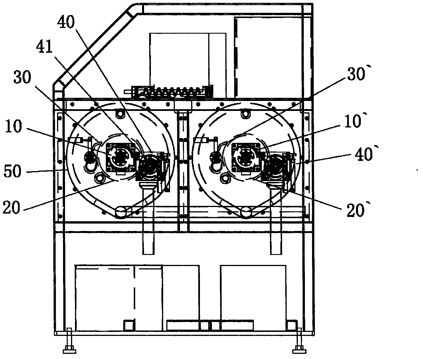
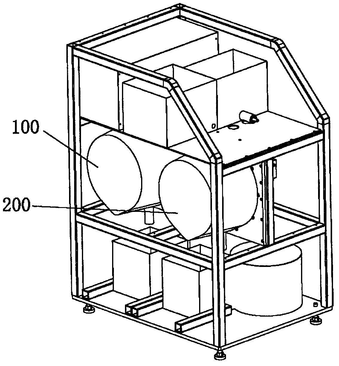
[0034] combined with Figure 1-4 , to further describe the present invention.
[0035] The present invention adopts following technical scheme:
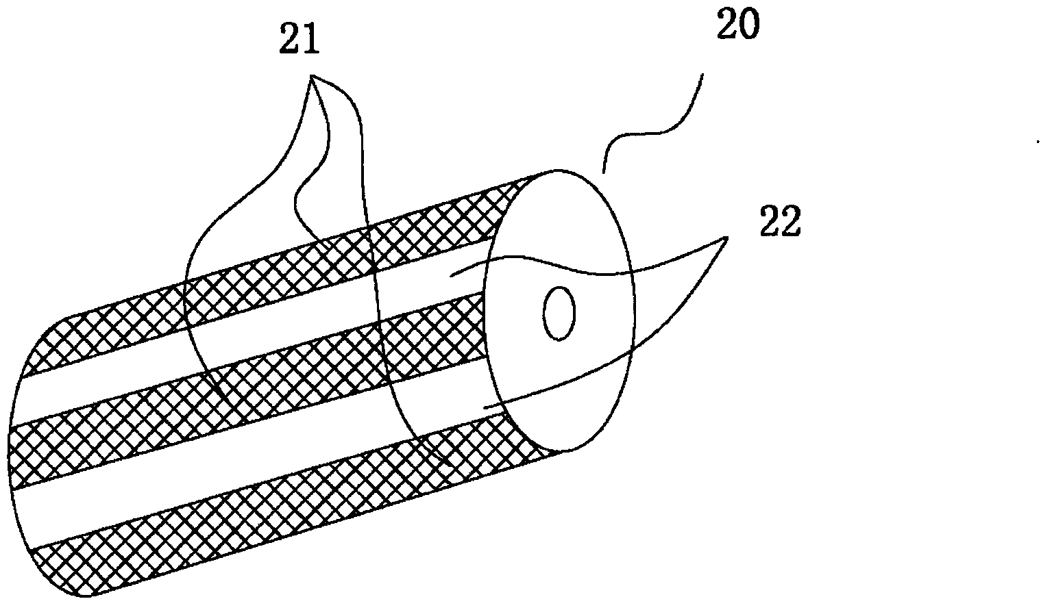
[0036] A magnetic mud separation and recovery equipment for cutting waste liquid, including: at least one set of magnetic mud recovery mechanism, the magnetic mud recovery mechanism includes: motor 10, drum 20, scraper 30 and separation recovery mechanism 40, the drum 20 is connected to the motor On the output end of 10 to realize rotation, on the surface of cylinder 20, be provided with several mutually spaced magnetic force intervals 21 and non-magnetic intervals 22, scraper 30 is fixedly arranged on the side of cylinder 20 and the cutter head of scraper 30 and cylinder 20 The surface corresponds to scrape the magnetic powder collected in the magnetic area 21 on the drum 20 to the non-magnetic area 22 , and the separation and recovery structure 40 is arranged beside the drum 20 to realize the separation and recovery of the magnetic powder in the non-magnetic area 22 on the drum 20 .
[0037] The present invention provides a kind of separation and recovery equipment to carry out the method for separation and recovery according to above equipment, and this method comprises the following steps:
[0038] Step 1a, the magnetic section 21 of the drum 20 absorbs the magnetic powder in the cutting waste liquid to the magnetic section 21;
[0039] In step 2b, the motor 10 drives the drum 20 to rotate, and the scraper 30 pushes the magnetic powder on the magnetic area 21 to the non-magnetic area 22;
[0040] In step 3c, the separation and recovery mechanism 40 sends away the magnetic powder on the non-magnetic section 22 to recover the magnetic powder.
[0041] Furthermore, the separation and recovery mechanism 40 includes a screw propeller 41 .
[0042] Furthermore, the magnetic zone 21 on the surface of the drum 20 is made of rare earth permanent magnet material.
[0043] Furthermore, the motor 10 is two servo motors, one of which is a slow-rotating scraping servo motor, and the other is a high-speed rotating centrifugal motor for centrifugally dehydrating the cutting oil liquid adsorbed on the drum 20. servo motor.
[0044] The present invention provides a kind of separation and recovery equipment to carry out the method for separation and recovery according to above equipment again, and this method comprises the following steps:
[0045] Step 1, the magnetic section 21 of the drum 20 in the first set of magnetic mud recovery mechanism 100 absorbs the magnetic powder in the cutting waste liquid to the magnetic section 21;
[0046] Step 2, the motor 10 in the first set of magnetic mud recovery mechanism 100 drives the drum 20 to rotate, and the scraper 30 pushes the magnetic powder on the magnetic area 21 to the non-magnetic area 22;
[0047] Step 3, the separation and recovery mechanism 40 in the first set of magnetic mud recovery mechanism 100 sends away the magnetic powder on the non-magnetic section 22 to recover the magnetic powder;
[0048] Step 4, dilute the magnetic powder recovered for the first time with water and then enter the second set of magnetic mud recovery mechanism;
[0049] Step five, the magnetic section of the drum 20' in the second set of magnetic mud recovery mechanism 200 absorbs the magnetic powder in the cutting waste liquid to the magnetic section;
[0050] Step 6, the motor 10` in the second set of magnetic mud recovery mechanism 200 drives the drum 20` to rotate, and the scraper 30` pushes the magnetic powder on the magnetic area to the non-magnetic area;
[0051] Step 7, the separation and recovery mechanism 40 ′ in the second set of magnetic mud recovery mechanism 200 sends away the magnetic powder in the non-magnetic area to recover the magnetic powder.
[0052] Furthermore, the magnetic mud recovery mechanism also includes a cavity 50 for containing cutting waste liquid, and the motor 10 , the roller 20 , the scraper 30 and the separation and recovery mechanism 40 are all arranged in the cavity.
[0053] Furthermore, there are two sets of magnetic mud recovery mechanisms to realize the separation and recovery of the magnetic powder recovered for the first time after being diluted with water.
[0054] According to the above equipment, the present invention provides a method for separation and recovery of the separation and recovery equipment, which is characterized in that the method comprises the following steps:
[0055]Step 1, the magnetic section 21 of the drum 20 absorbs the magnetic powder in the cutting waste liquid to the magnetic section 21;
[0056] Step 2, the scraping servo motor drives the drum 20 to rotate, and the scraper 30 pushes the magnetic powder on the magnetic section 21 to the non-magnetic section 22;
[0057] Step 3, the separation and recovery mechanism 40 sends away the magnetic powder on the non-magnetic section 22 to recover the magnetic powder;
[0058] Step 4: The control chip controls the centrifugal servo motor to drive the drum 20 to rotate at a high speed, and the silicon carbide sand and cutting oil are separated from the drum 20 with the magnetic force range 21 by using centrifugal force and inertia.
[0059] Experimental data:
[0060] a. The original cutting fluid: silicon carbide sand 60kg, accounting for 60%; cutting oil 40kg, accounting for 40%;
[0061] b. Cutting fluid when the magnetic powder is saturated: silicon carbide sand 60kg accounts for 56.1%; cutting oil 40kg accounts for 37.4%; magnetic powder 7kg accounts for 6.54%;
[0062] c. The magnetic mud reclaimed by the magnetic mud separation and recovery equipment of the present invention: 3.9kg of silicon carbide sand accounts for 33.5%; 1.26kg of cutting oil accounts for 10.8%; 6.5kg of magnetic powder accounts for 55.7%;
[0063] d. The cutting fluid after magnetic mud is recovered by the magnetic mud separation and recovery equipment of the present invention: 56.1 kg of silicon carbide sand accounts for 58.84%; 38.74 kg of cutting oil accounts for 40.63%; 0.5 kg of magnetic powder accounts for 0.52%.
[0064] After adopting the structure of the present invention, the present invention separates and recycles the magnetic powder in the cutting fluid in real time, so that the cutting fluid can be recycled multiple times when the abrasive silicon carbide does not need to be replaced, so as to ensure product quality, improve production efficiency, and reduce production costs. Purpose.
[0065] The above content is a further detailed description of the present invention in conjunction with specific preferred embodiments, and it cannot be assumed that the specific implementation of the present invention is limited to these descriptions. For those of ordinary skill in the technical field of the present invention, without departing from the concept of the present invention, some simple deduction or replacement can be made, which should be regarded as belonging to the protection scope of the present invention.

PUM

no PUM

Description & Claims & Application Information

We can also present the details of the Description, Claims and Application information to help users get a comprehensive understanding of the technical details of the patent, such as background art, summary of invention, brief description of drawings, description of embodiments, and other original content. On the other hand, users can also determine the specific scope of protection of the technology through the list of claims; as well as understand the changes in the life cycle of the technology with the presentation of the patent timeline. Login to view more.

Similar technology patents

Manufacturing method of concrete precast pile

Owner:山东三原混凝土桩业有限公司

Automated 5G (the 5th generation wireless systems) base station ceramic filter production line

InactiveCN109904581AGuarantee product qualityGuaranteed production efficiency
Owner:泉州佰桀智能制鞋设备研究院有限公司

Classification and recommendation of technical efficacy words

  • Increase productivity
  • Guarantee product quality

Preparation method of super-retarding type polycarboxylate superplasticizer

ActiveCN103848944AIncrease productivityUniform product
Owner:KZJ NEW MATERIALS GROUP CO LTD

Artificial intelligence sheet metal part producing system

ActiveCN105642781AGuarantee product qualityAvoid Dimensions
Owner:XUZHOU DKEC ELECTRICAL TECH

Fresh-keeping shish kebab and preparation method thereof

InactiveCN102948771AGuarantee product qualityinhibit microbial growth
Owner:INNER MONGOLIA MENGYISA JINSHAN FOOD CO LTD
Why Eureka
Try Eureka