
A kind of production device of magnesium alloy fiber wire

A production device and technology of fiber filaments, applied in the field of metal fiber filament production devices, can solve problems such as high cost, limited application, and influence on the use effect, and achieve the effects of stable quality, easy operation, and good length

Inactive Publication Date: 2015-11-18
YANSHAN UNIV
View PDF6 Cites 0 Cited by
  • Summary
  • Abstract
  • Description
  • Claims
  • Application Information

AI Technical Summary

Problems solved by technology

For example, Shen Xingquan (CN1857859) of North University of China designed a continuous cutting device to process metal fibers. Although this method has high processing accuracy, the elongation of the fibers produced is low, which affects the use effect.
Gong Weihong (CN101886300A) of Hunan Huibo Metal Materials Co., Ltd. mainly uses the method of cluster drawing and compounding metal wires in auxiliary materials to prepare metal fibers. Although the surface quality of the produced fibers is good, it is only suitable for high plasticity. materials, and after multiple heat treatments in the middle, the process is more complicated and the cost is higher
Zhao Weitao (CN101886300A) of China Aluminum Co., Ltd. designed a metal fiber production device, which can produce both short fibers and long fibers, and meets the needs of purification and protection solutions, but the processing equipment of this equipment is relatively complicated. The process and technical requirements are high, and the surface quality of fiber molding is not easy to control, which limits the further application of this device

Method used


Image

  • A kind of production device of magnesium alloy fiber wire
  • A kind of production device of magnesium alloy fiber wire

Examples


Embodiment Construction

[0015] The present invention will be described below with reference to the accompanying drawings. It should be understood that the detailed structure of the magnesium alloy fiber filament production device of the present invention is not limited to the following examples.

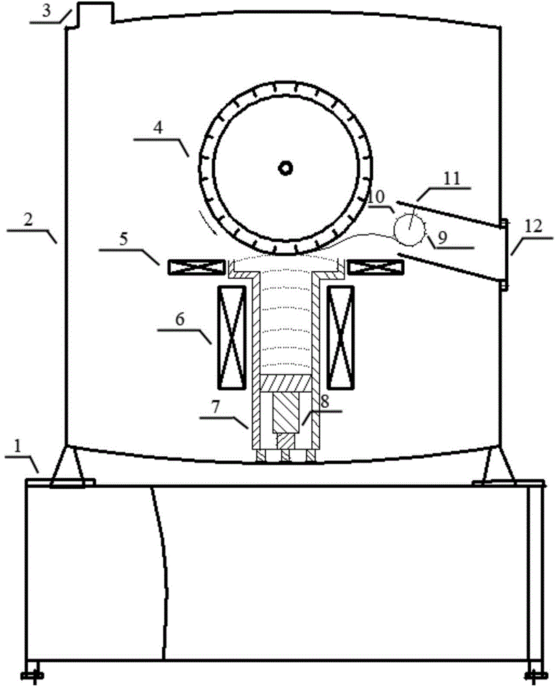
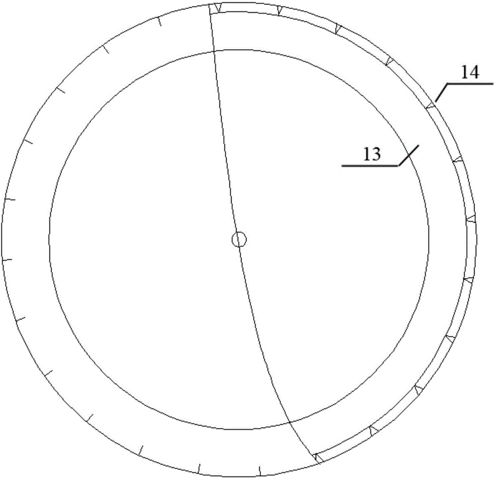
[0016] in the attached figure 1 In the schematic diagram of the magnesium alloy fiber filament production device shown, the vacuum furnace body 2 is fixed on the base 1, the vacuum valve 3 is arranged above the furnace body, and the spinning wheel 4 is arranged at the center of the furnace body, as shown in FIG. figure 2 As shown, the material used for the spinning wheel is alumina dispersion strengthened copper, and the inner cavity is filled with high-pressure cold water 13 as a medium, and a number of equidistant V-shaped grooves 14 are arranged on the outer edge of the wheel along the direction of the generatrix of the wheel. , and the chute equal to the number of V-shaped grooves is provided on the f...


PUM


Abstract

The invention provides a device for producing magnesium alloy cellosilk. A vacuum furnace body of the device is fixed to a base. A vacuum valve is arranged above the furnace body. A silk throwing wheel is arranged at the center of the furnace body. A cavity inside the silk throwing wheel is filled with high-pressure cold water as media. A plurality of equidistant V-shaped grooves are formed in the outer edge of the silk throwing wheel in the bus direction of the silk throwing wheel. Skewed grooves with the same number as the V-shaped grooves are formed in the wheel edge in the axial direction. A raw material chamber is arranged below the silk throwing wheel. A piston device is arranged at the bottom of a cavity of the raw material chamber. An upper induction coil and a lower induction coil are arranged on the upper portion and the lower portion of the outer side of the raw material chamber in an encircling mode respectively. A receiving barrel is arranged on one side of the vacuum furnace body. A receiving wheel is arranged in a cavity of the receiving barrel. Elastic sheets are arranged on the receiving wheel. The device is easy to operate, capable of well controlling forming of fiber and stable in quality, and the obtained magnesium alloy cellosilk can meet the requirements for the diameter and the length.

Description

technical field [0001] The invention belongs to the field of metal material preparation, in particular to a production device for metal fiber filaments. Background technique [0002] Metal fiber and its products are new industrial materials and high-tech and high value-added products developed in the past 20 years. It not only has the softness of chemical fibers, synthetic fibers and their products, but also has the excellent thermal conductivity, electrical conductivity and corrosion resistance of metal itself. , high temperature resistance and other characteristics. As a new fiber material, metal fiber has been valued by all walks of life. At present, domestic metal fiber products are mainly stainless steel microwires and iron-chromium-aluminum fibers, and there are few related reports on magnesium alloy fibers. Magnesium alloys have low density, high specific strength and good biocompatibility, and are a hotspot in the research of structures and biomaterials. Magnesium...

Claims


Application Information

Patent Timeline
Patent Type & Authority Patents(China)
IPC IPC(8): B22D11/06
Inventor 彭秋明付辉李慧
Owner YANSHAN UNIV
Learn More