
Oscillator circuit with temperature compensation function

A temperature compensation and oscillator technology, applied in the circuit field, can solve the problems of limited selection range, inaccurate matching, large discreteness, etc.

Inactive Publication Date: 2014-05-14
CHIPSEA TECH SHENZHEN CO LTD
View PDF8 Cites 7 Cited by
  • Summary
  • Abstract
  • Description
  • Claims
  • Application Information

AI Technical Summary

Problems solved by technology

However, when using a resistor with a temperature coefficient of opposite sign to compensate the temperature coefficient, the two resistors are usually not process-dependent, so the resistance value of one of the resistors usually varies greatly with respect to the other, for example, it can reach + / -30%; and different types of resistors cannot be matched, which also leads to uncertainty in the proportional relationship between the resistance values; and the change in the resistance relationship between the two resistors will directly lead to the offset of temperature compensation, resulting in compensation After the oscillator output clock frequency temperature coefficient is still large
In short, when using two kinds of resistors to compensate the temperature coefficient, there are problems such as large variations with the process, large dispersion, and unsatisfactory compensation effects.
[0003] In the patent application 201110289103.0, an oscillator with temperature compensation realized by only one temperature coefficient resistor is disclosed, which avoids the problem of inaccurate matching between two devices with different temperature coefficients, but the The structure limits that the resistors used must have a negative temperature coefficient, thus limiting the selection range of the resistors; in addition, the structural circuit published in the application is at V UPPER , V LOWER The two voltages are charged and discharged, and the inaccurate matching of the charge and discharge current will cause the duty cycle of the oscillator to become poor when outputting a clock signal with a high frequency (such as >10MHz)

Method used


Image

  • Oscillator circuit with temperature compensation function
  • Oscillator circuit with temperature compensation function
  • Oscillator circuit with temperature compensation function

Examples


Embodiment Construction

[0037] In order to make the object, technical solution and advantages of the present invention clearer, the present invention will be further described in detail below in conjunction with the accompanying drawings and embodiments. It should be understood that the specific embodiments described here are only used to explain the present invention, not to limit the present invention.

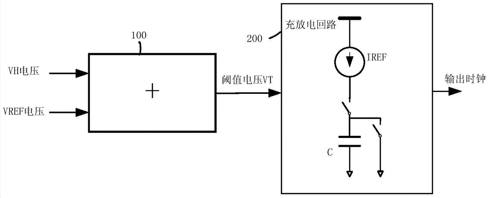
[0038] figure 1 As shown, the oscillator circuit with temperature compensation realized by the present invention, its circuit schematic diagram at least includes:

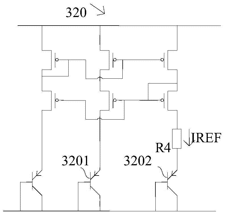
[0039] A reference current generating circuit for generating a current IREF with a first-order temperature coefficient Ki;

[0040] a reference source for providing a reference voltage VREF;

[0041] A VH voltage generating circuit providing a voltage VH with a first-order positive temperature coefficient Kv;

[0042] A voltage adding circuit 100, used to add the reference voltage and the VH voltage to generate a threshold voltage VT...


PUM


Abstract

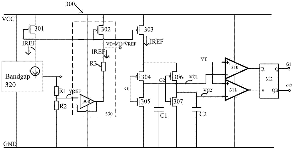
The invention discloses an oscillator circuit with a temperature compensation function. The oscillator circuit comprises a reference current generation circuit, a reference source, a VH voltage generation circuit, a voltage adding circuit for adding a reference voltage to a VH voltage, and a charging and discharging control unit. The charging and discharging control unit takes a threshold voltage VT as a charging and discharging threshold value, and controls a current IREF to charge or discharge a capacitor C between the threshold voltage and the ground. When the capacitor C is charged to reach the threshold voltage, logic output reverse is triggered and repeatedly conducted. By means of the oscillator circuit, the output clock frequency is compensated for along with the change of the temperature through a resistor with the positive temperature coefficient, the temperature coefficient of the output clock frequency is small, the discreteness is small, the temperature compensation effect is improved, transfer between different processes is facilitated, and the oscillator circuit is suitable for large-scale mass production and application; meanwhile, an output clock can still have a good duty ratio at the high frequency.

Description

technical field [0001] The invention belongs to the field of circuits, in particular to an oscillator circuit. Background technique [0002] Traditional on-chip oscillators generally adopt an RC oscillator structure, and the oscillation frequency is related to RC. Since the on-chip resistor R usually has a large temperature coefficient, the output clock frequency of the RC oscillator also has a large temperature coefficient. Two resistors with temperature coefficients of opposite signs are usually used to combine into one resistor with a zero temperature coefficient (usually a first-order approximation of zero), making the clock frequency independent of temperature. However, when using a resistor with a temperature coefficient of opposite sign to compensate the temperature coefficient, the two resistors are usually not process-dependent, so the resistance value of one of the resistors usually varies greatly with respect to the other, for example, it can reach + / -30%; and ...

Claims


Application Information

Patent Timeline
Patent Type & Authority Applications(China)
IPC IPC(8): H03B5/04
Inventor 李晓
Owner CHIPSEA TECH SHENZHEN CO LTD
Learn More