Natural gas recycling method for compressed natural gas stations

A technology for compressing natural gas and natural gas, which is applied in the container filling method, the container discharging method, and the equipment loaded into the pressure vessel, etc., can solve the problems of natural gas waste and environmental pollution, and achieves reduction of hidden safety hazards, protection of environmental pollution, and avoidance of resources. wasteful effect

Inactive Publication Date: 2014-05-28
CHINA PETROLEUM & CHEM CORP +1
View PDF5 Cites 11 Cited by
  • Summary
  • Abstract
  • Description
  • Claims
  • Application Information

AI Technical Summary

Problems solved by technology

[0007] The technical problem to be solved by the present invention is the problem of natural gas waste and environmental pollution in the prior art, and a new natural gas recycling method for compressed natural gas filling stations is provided

Method used


Image

  • Natural gas recycling method for compressed natural gas stations
  • Natural gas recycling method for compressed natural gas stations

Examples


Embodiment 1

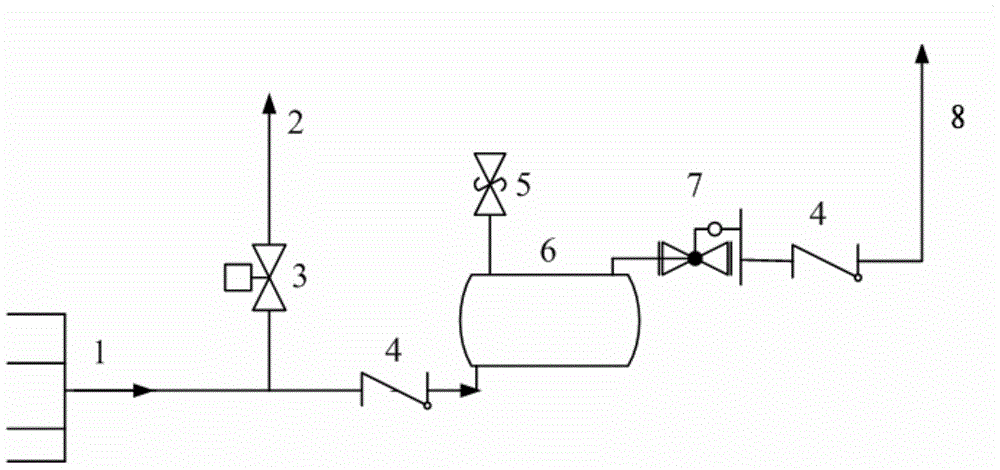
[0022] figure 1 It is one of the schematic flow charts of the method of the present invention. The incoming gas from the venting pipe of the air filling gun merges into the gas collecting main pipe 1. At this time, the control valve 3 on the venting pipeline 2 is closed, and the recovered natural gas passes through the one-way After the isolation valve 4 enters the buffer tank 6 for buffering, it enters the natural gas compressor through the pressure regulator 7 through the one-way isolation valve. The operating conditions of the buffer tank 6 are as follows: the temperature is normal temperature, and the pressure is normal pressure with gauge pressure gauge. When the recovery pipeline pressure drops to the same pressure as the gas pipeline before the compressor, the control valve 3 is opened, and the remaining gas is vented to complete a recovery process.

Embodiment 2

[0024] According to the conditions and steps described in Example 1, the incoming gas from the venting pipe of the air filling gun merges into the gas collecting main pipe 1. At this time, the control valve 3 on the venting pipeline 2 is closed, and the recovered natural gas is isolated in one direction. After the valve 4 enters the buffer tank 6 for buffering, it enters the natural gas compressor through the pressure regulator 7 through the one-way isolation valve. The operating conditions of the buffer tank 6 are as follows: the temperature is 90° C., and the pressure is 25 MPa in terms of gauge pressure. When the recovery pipeline pressure drops to the same pressure as the gas pipeline before the compressor, the control valve 3 is opened, and the remaining gas is vented to complete a recovery process.

Embodiment 3

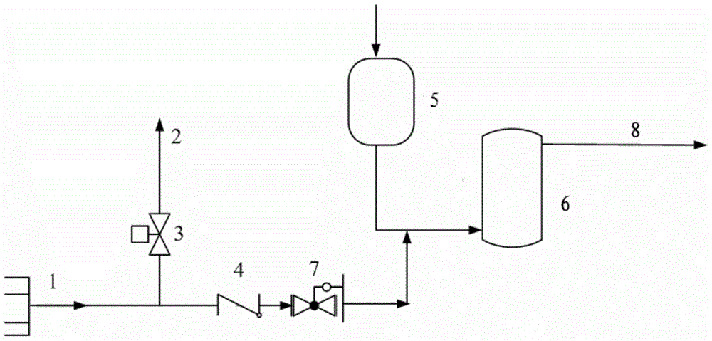
[0026] figure 2 It is the second schematic flow chart of the method of the present invention. The incoming gas from the venting pipe of the air filling gun merges into the gas collecting main pipe 1. At this time, the control valve 3 on the venting pipeline 2 is closed, and the recovered natural gas passes through the one-way The isolation valve 4 enters the buffer tank 6 in front of the compressor through the pressure regulator 7 for buffering, and then enters the compressor together with the natural gas from the pressure regulating metering system or the desulfurization system 5 . The operating conditions of the buffer tank 6 are as follows: the temperature is 50° C., and the pressure is 10 MPa in terms of gauge pressure. When the recovery pipeline pressure drops to the same pressure as the gas pipeline before the compressor, the control valve 3 is opened, and the remaining gas is vented to complete a recovery process.


PUM


Abstract

The invention relates to a natural gas recycling method for compressed natural gas stations, and mainly solves the problems that in the prior art, natural gas is wasted and environmental pollution is caused. The natural gas recycling method well solves the problems by adopting the technical scheme that natural gas from a recycling pipeline is divided into at least two paths after passing through a gas collecting main pipe, one path is emptied through an emptying pipeline, the other path enters a buffer tank, the natural gas from the buffer tank is fed into a compressor, and when the pressure of the recycling pipeline is reduced to be consistent with that of a gas pipeline in front of the compressor, a control valve of the emptying pipeline is opened to empty the natural gas. The method can be applied to compressed natural gas stations.

Description

technical field [0001] The invention relates to a method for recovering and utilizing natural gas in a compressed natural gas filling station. technical background [0002] In the present compressed natural gas filling station, after adding gas to the automobile cylinder, there is still about 1-2 liters of residual natural gas with a pressure of 20MPa in the pipeline between the gun head of the air filling gun and the control valve. In order to avoid danger, usually after the section of gas is emptied to the atmosphere, the gas filling process is considered to be over after the gas filling gun is removed. As a dangerous chemical, natural gas is flammable and explosive. Repeated discharge is easy to accumulate in gas filling stations, posing a major safety hazard. As a non-renewable energy source, natural gas is directly discharged into the atmosphere, causing a serious waste of resources. In addition, methane, as a greenhouse gas, also destroys the ozone layer and pollutes ...

Claims


Application Information

Patent Timeline
Patent Type & Authority Applications(China)
IPC IPC(8): F17C5/06F17C13/02F17C13/04
Inventor 王全国武志峰刘昌华张广文党文义韩中枢
Owner CHINA PETROLEUM & CHEM CORP
Why Eureka
Try Eureka