Solar energy cooker system

A solar cooker and solar collector technology, which is applied to solar heating systems, solar thermal energy, solar thermal power generation, etc., can solve the problems of difficulty in troubleshooting, increase water storage, and consume thermal energy, saving production materials and reducing operation. cost, the effect of improving thermal efficiency

Inactive Publication Date: 2014-05-28
赵景田
View PDF6 Cites 7 Cited by
  • Summary
  • Abstract
  • Description
  • Claims
  • Application Information

AI Technical Summary

Problems solved by technology

[0002] The existing solar cooker system has the following disadvantages: 1. The cooker must exceed the height of the outdoor header, otherwise it cannot be used normally, so steps and brackets need to be built, which brings great inconvenience to the indoor cooks
2. The circulation system is often in a state of high water temperature, and it is easy to scale after a long time, which affects normal use
Therefore, the circulation system uses soft water provided by a water softener, which is not only costly but also polluting.
3. The manufacture of stoves and cooking utensils requires relatively complex production processes and a large number of equipment and molds
4. The electric reversing valve system is composed of a circuit control panel, etc., which is costly and difficult to troubleshoot if a fault occurs
5. After each meal is made, turn the reversing valve so that the water in the return pipe enters the inner tank of the header. Because the temperature suddenly changes from high tem...

Method used


Image

  • Solar energy cooker system
  • Solar energy cooker system
  • Solar energy cooker system

Examples


Embodiment Construction

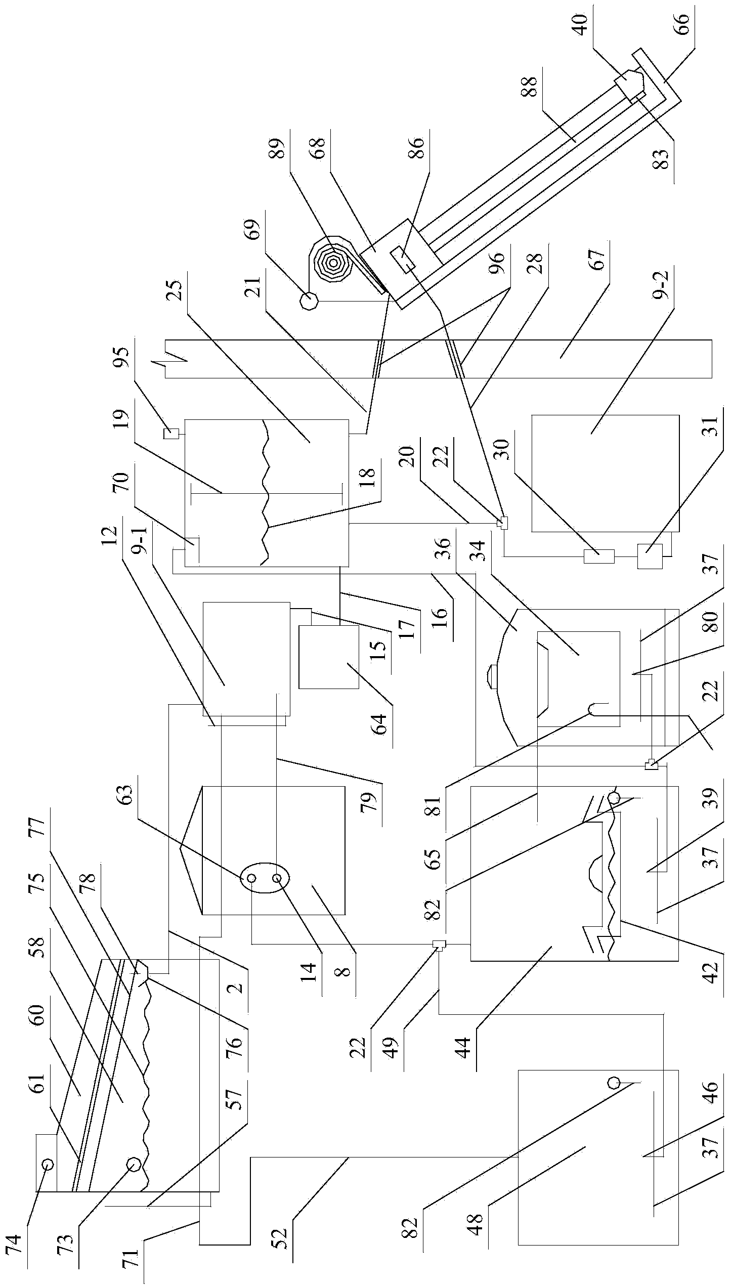
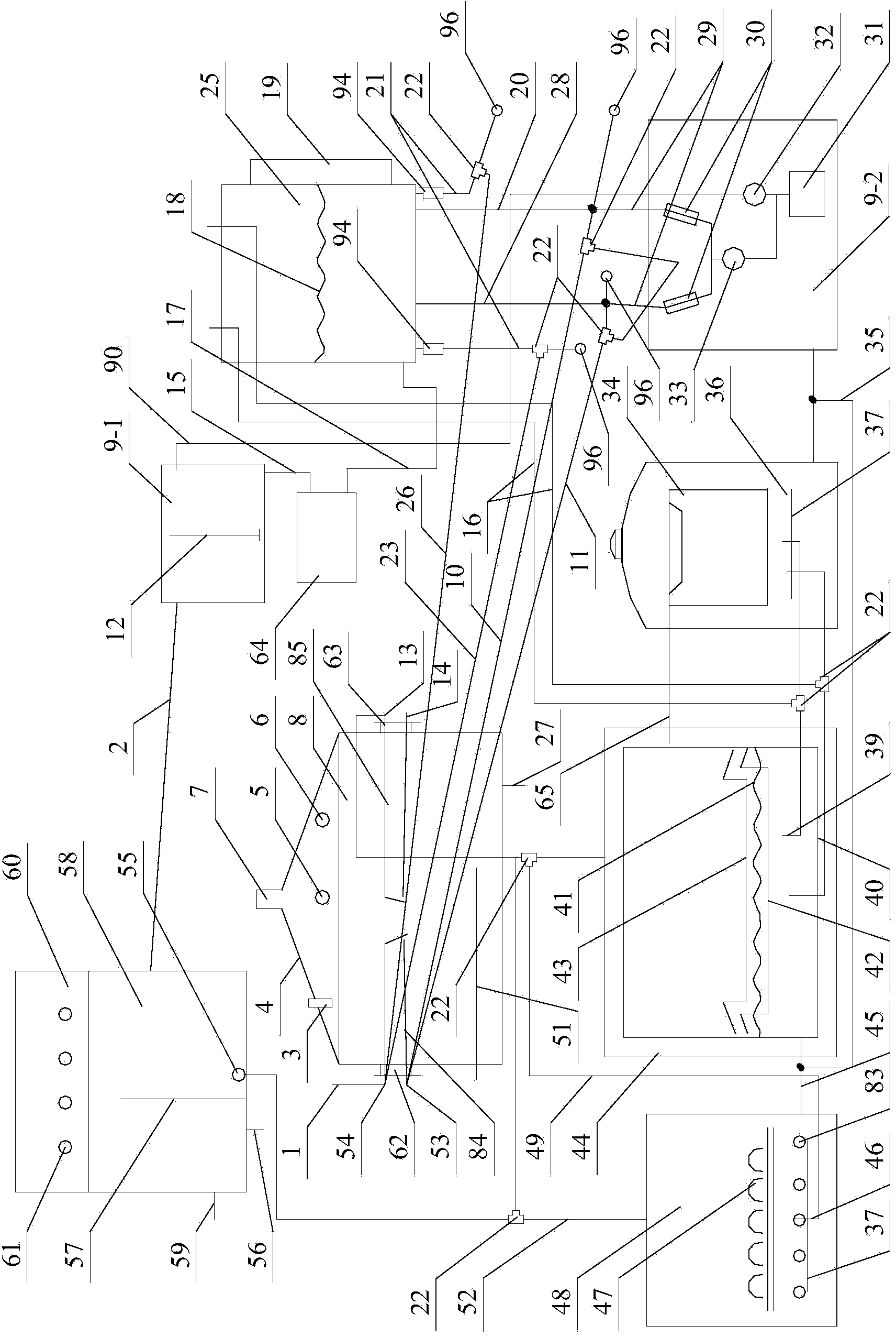
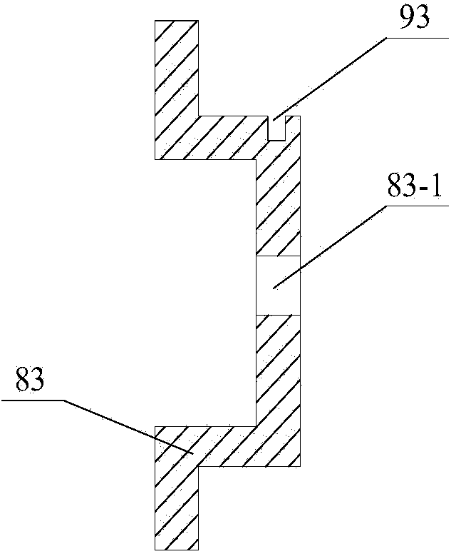
[0015] The present invention will be described in further detail below in conjunction with the accompanying drawings: the present embodiment is implemented on the premise of the technical solution of the present invention, and detailed implementation is provided, but the protection scope of the present invention is not limited to the following embodiments.

[0016] Such as Figure 1 to Figure 6As shown, a solar cooker system involved in this embodiment includes: a first pipeline 2, a hot water tank 8, a high water tank 9-1, a low water tank 9-2, a second pipeline 10, a third pipeline 11, a water level Sight pipe 12, fifth pipe 15, steam pipe 16, seventh pipe 17, water level display glass pipe 19, first return water pipe 20, upper water and steam pipe 21, fourth pipe 23, steam-water separator 25, eighth pipe 26. The second return pipe 28, the electric heater 30, the water pump 31, the first valve 32, the second valve 33, the ninth pipeline 35, the cooking barrel 36, the electri...


PUM


Abstract

The invention provides a solar energy cooker system. A water feeding and steam pipeline is connected between a header and a steam separator. The lower portion in a cooking barrel, the lower portion in a cooking cabinet and the lower portion in a steaming cabinet are provided with electric heating pipes. One end of a fourth pipeline is communicated with a hot water tank, and the other end of the fourth pipeline is communicated with the steam separator and a solar energy collector. A cooker can be directly placed on the ground, a step and a support are omitted, and operation of kitchen staff is greatly facilitated. After a distilled water generator is modified, pollution is avoided, the maintenance frequency is extremely low, and water quality is better. The electric heating pipes are arranged at the bottom of a water returning pipeline, the bottom of the cooking cabinet, the bottom of the cooking barrel and the bottom of the steaming cabinet, the temperature of water in the system can be fast raised, and when it becomes cloudy suddenly in the cooking process, food can be cooked forcefully. Before water in the pipelines is not frozen, a valve is opened, so that water in the pipelines flows into a water tank, the water in the water tank is injected into the system again in the morning of the next day through a water pump, and therefore blocking, caused by freezing, of a circulation pipeline is avoided.

Description

technical field [0001] The invention relates to a solar cooker system and belongs to the technical field of solar cooker systems. Background technique [0002] The existing solar cooker system has the following disadvantages: 1. The cooker must exceed the height of the outdoor header, otherwise it cannot be used normally, so steps and brackets need to be built, which brings great inconvenience to the indoor cooks . 2. The circulation system is often in a state of high water temperature, which is prone to fouling after a long time, affecting normal use. Therefore, the circulation system uses the soft water provided by the water softener, which is not only expensive but also polluting. 3. The manufacture of stoves and cooking utensils requires relatively complex production processes and a large number of equipment and molds. 4. The electric reversing valve system is composed of a circuit control panel, etc., which is costly and difficult to troubleshoot if a fault occurs. ...

Claims


Application Information

Patent Timeline
IPC IPC(8): F24J2/00A47J27/04A47J27/56F24S20/30
CPCY02A40/926Y02B40/18Y02E10/40
Inventor 赵景田
Owner 赵景田
Why Eureka
Try Eureka