

Epoxy resin compound and radiant heat circuit board using the same
A technology of epoxy resin and composition, which is applied in the direction of circuit substrate materials, printed circuits, circuit heating devices, etc., can solve problems such as difficult handling, weak heat resistance, mechanical strength and tension, and achieve improved voltage resistance and ensure Coating performance, effect of improving dispersion stability
- Summary
- Abstract
- Description
- Claims
- Application Information
AI Technical Summary
Problems solved by technology
Method used
Image


Examples
Embodiment approach
[0070] Hereinafter, the present disclosure will be described in more detail through embodiments.
[0071] The thermal conductivity was measured by an abnormal heat conduction scheme using a thermal conductivity meter LFA447 manufactured by NETZSCH.
[0072]The epoxy resin composition is coated on the Al substrate and cured, and then the Al substrate is bent at 180 degrees and returned to the original position, and the peeling performance of Al is represented by the delamination degree (delmaination degree) of the epoxy resin composition . Record when the degree of delamination is less than 0.2 cm. Record when the degree of delamination is in the range of 0.2 cm to 1 cm. Record when the degree of delamination is 1 cm or greater.
Embodiment approach 1
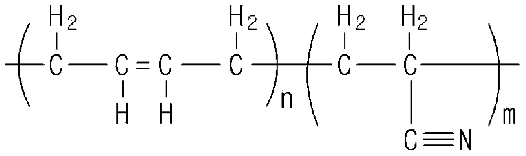
[0074] 3w% bisphenol F, 2w% o-cresol novolac, 1w% 4,4' oxobis (N-(4-(epoxy-2-ylmethoxy) benzylidene) aniline ( 4,4'oxybis(N-(4-(oxiran-2-ylmethoxy)benzylidene)-aniline)), 1w% NC-3000H epoxy resin (Nippon Kayaku co.,Ltd), 1w% DAS curing agent, 1.5w% of the DAS curing accelerator, 0.25w% of BYK-W980 and 0.25w% of the rubber additive represented in Chemical Formula 2 were mixed with each other and stirred at a temperature of 40° C. for 10 minutes. Thereafter, into the mixture was introduced 90w% aluminum oxide inorganic filler, and stirred at room temperature for 20 minutes to 30 minutes to prepare the crystalline epoxy resin composition of embodiment 1.
[0075] The thermal conductivity was measured by an anomalous thermal conductivity method using a thermal conductivity meter LFA447 manufactured by NETZSCH.
[0076] The heat of fusion was measured at a heating rate of 10 / min using a differential scanning calorimeter (DSC Q100 manufactured by TA Instruments Waters).
[0077] G...
Embodiment approach 2
[0079] 3w% bisphenol F, 2w% o-cresol novolac, 1w% 4,4' oxobis (N-(4-(epoxy-2-ylmethoxy)benzylidene) aniline, 1w% of NC-3000H epoxy resin (Nippon Kayaku co.,Ltd), 1w% of DAS curing agent, 1.5w% of DAS curing accelerator, 0.15w% of BYK-W980 and 0.35w% of chemical formula 2 The rubber additives are mixed with each other and stirred at a temperature of 40 ° C for 10 minutes. Then, 90w% of alumina inorganic filler is introduced into the mixture, and stirred at room temperature for 20 minutes to 30 minutes to obtain the crystal of embodiment 2 epoxy resin composition.
[0080] The thermal conductivity was measured by an anomalous thermal conductivity method using a thermal conductivity meter LFA447 manufactured by NETZSCH.
[0081] The heat of fusion was measured at a heating rate of 10 / min using a differential scanning calorimeter (DSC Q100 manufactured by TA Instruments Waters).
[0082] Glass transition temperature was measured using a DSC Q100 calorimeter manufactured by TA In...
PUM
 Abstract
Description
Claims
Application Information