Cold-rolled strip welding technology method

A welding process, a technology of cold-rolled steel strip, applied in the resistance welding process of steel strip, the production process field of cold-rolled steel strip, can solve the problem that the weld cannot be normalized by itself, the toughness of the weld seam, the limitation of the thickness range of the welded steel strip, and the welding Smoke and dust are harmful to workers' health and other problems, and achieve the effect of eliminating residual welding stress, fast welding speed and reliable method

Inactive Publication Date: 2014-06-04
TIANJIN YIBO STEEL MAKING
View PDF4 Cites 6 Cited by
  • Summary
  • Abstract
  • Description
  • Claims
  • Application Information

AI Technical Summary

Problems solved by technology

The original technology uses a manual arc welding device. The shortcomings of the original technology are: 1. The speed is slow (0.18-0.22m / min) and the work efficiency is low; 2. The quality of the weld seam is unstable. Limitation (thickness ≥ 0.5mm), 4. The weld seam cannot be normalized by itself. The weld seam has poor toughness and low strength. 5. Welding fume is harmful to the health of workers

Method used


Image

  • Cold-rolled strip welding technology method
  • Cold-rolled strip welding technology method
  • Cold-rolled strip welding technology method

Examples


Embodiment 1

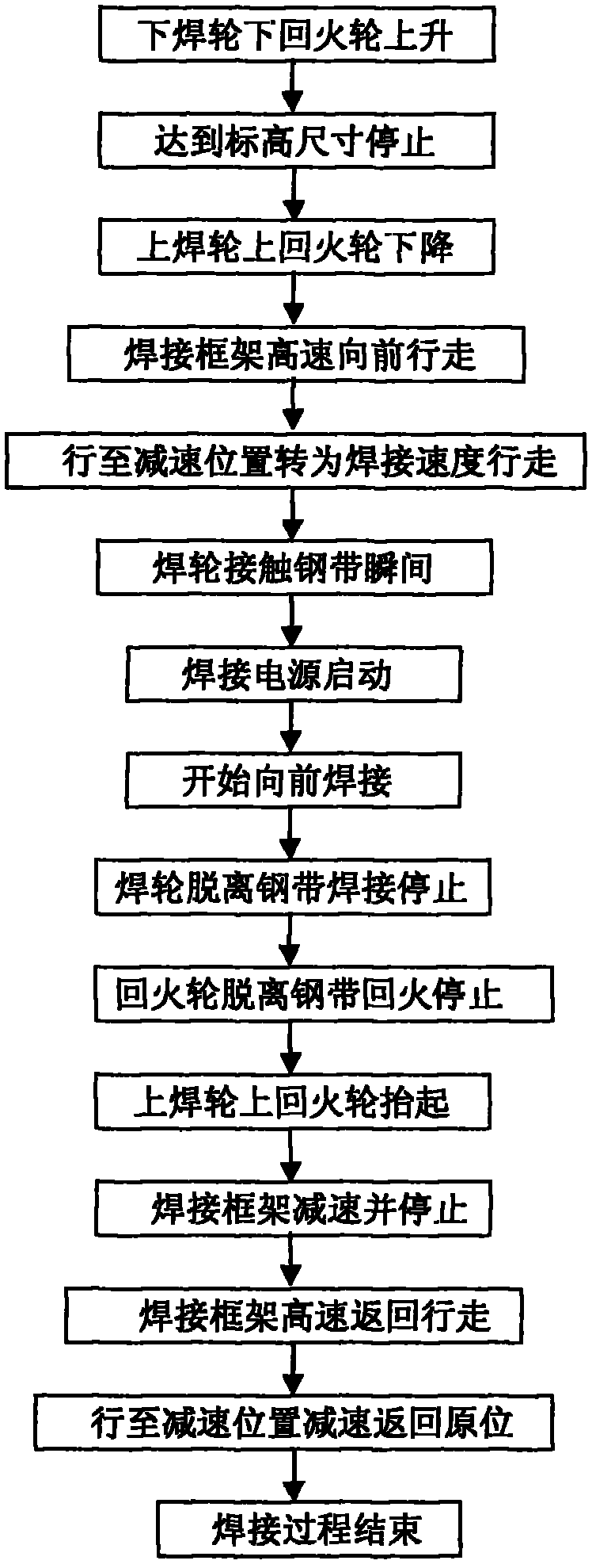
[0018] The lower welding wheel and the lower tempering wheel rise → reach the elevation and stop → the upper welding wheel and the upper tempering wheel go down → the welding frame moves forward at high speed → travel to the deceleration position and turn to the welding speed → the moment the welding wheel touches the steel strip → the welding power starts →Start forward welding→Welding wheel breaks away from the steel strip and welding stops→Tempering wheel breaks away from the steel strip and stops tempering→The upper welding wheel and upper tempering wheel lift up→Welding frame decelerates and stops→Welding frame returns to walk at high speed→Walk to decelerate The position decelerates and returns to the original position → the welding process ends.

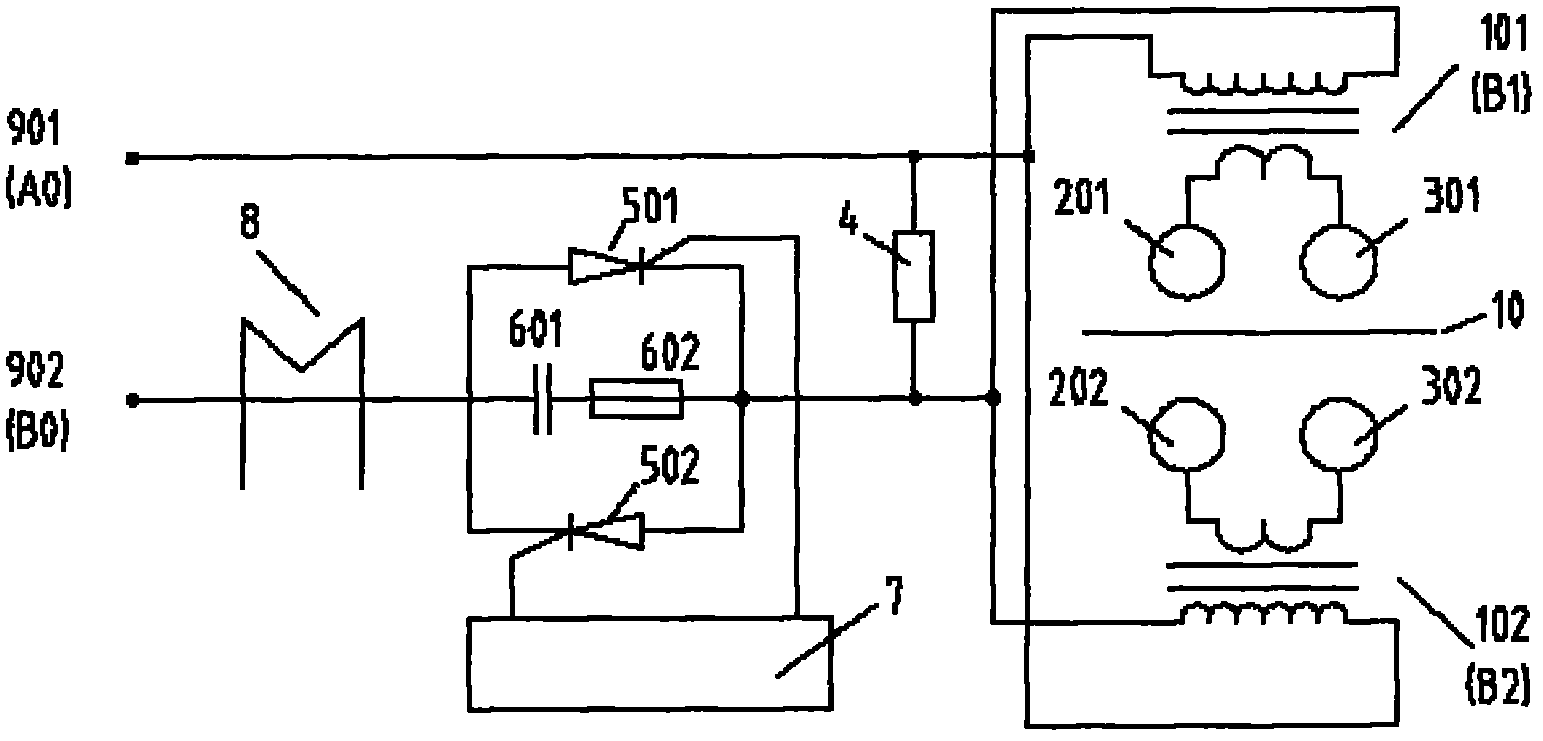
[0019] The welding frame walks forward with the upper welding wheel 201, the lower welding wheel 202, the upper tempering wheel 301, and the lower tempering wheel 302; When the welding transformer 101 (B1), 102 (B2) is powered...

Embodiment 2

[0021] The welding frame walks forward with the upper welding wheel 201, the lower welding wheel 202, the upper tempering wheel 301, and the lower tempering wheel 302; On, welding transformers 101 (B1), 102 (B2) are energized on the primary side, and the secondary side circuit is closed. The current flows through the steel strip 10 and generates heat through the resistance of the steel strip itself. ;When the welding wheels 201, 202 are separated from the steel strip, the welding stops, and the tempering stops when the tempering wheels 301, 302 are separated from the steel strip, and the upper welding wheel 201 and the upper tempering 301 wheel are lifted; the welding frame decelerates and stops; the welding frame returns to walk at a high speed , go to the deceleration position and decelerate to return to the original position; the welding process is over. In the schematic diagram, resistor 4 is an absorbing resistor, which is equivalent to the load as a buffer; RC circuits 6...


PUM


Abstract

The invention relates to a cold-rolled strip welding technology method. A welding framework drives an upper welding wheel, a lower welding wheel, an upper tempering wheel and a lower tempering wheel to walk forwards; the instant the upper and the lower welding wheels are in contact with a steel belt, controlled silicon is closed through a trigger circuit, an original edge of a welding transformer is powered on, a loop of an auxiliary edge of the welding transformer is closed, The current flows through the steel belt to act to generate heat through the resistance of the steel belt, and when the heat is continuously accumulated to enable metal on the welding portions to be combined through fusing; when the welding wheels separate away from the steel belt, welding is stopped; when the fire retuning wheels separate away from the steel belt, tempering is stopped, and the upper welding wheel and the upper tempering are lifted; the welding framework is decelerated and stopped; the welding framework returns at a high speed to walk to the deceleration position to decelerate to return to the original position, and the welding process is over; as shown in the attached chart 2, the resistor is a sucking resistor and equivalently serves as a load to have the buffering effect; the resistance-capacitance circuit is resistance-capacitance sucking protection controlled silicon; a mutual inductor compensates for sampled signals.

Description

technical field [0001] The invention belongs to the field of metal material welding, and relates to a resistance welding process method for steel strips, and is especially suitable for the production process of cold-rolled steel strips. Background technique [0002] Welding is a permanent connection of materials to become a structural manufacturing technology with a given function. It is one of the three key technologies of modern manufacturing and a key technology for supporting my country to become a manufacturing power. Welding can be divided into electrode arc welding, submerged arc welding, gas metal arc welding, tungsten inert gas shielded welding, gas welding, plasma arc welding, resistance welding, etc. Welding technology is widely used in machinery, electronics, chemical industry, home appliances, automobiles, shipbuilding, aviation, aerospace and other fields. Almost all products rely on welding technology to varying degrees in production. Welding has penetrated in...

Claims


Application Information

Patent Timeline
Patent Type & Authority Applications(China)
IPC IPC(8): B23K11/06B23K11/36C21D9/50
CPCB23K11/061B23K11/24B23K2101/16C21D9/50
Inventor 宋书成齐立峰
Owner TIANJIN YIBO STEEL MAKING
Why Eureka
Try Eureka