

Tea leaf high-voltage electrostatic field dryer
A high-voltage electrostatic field and drying machine technology, which is applied in the field of tea drying machines, can solve problems such as long drying time, tea shape change, and tea chlorophyll damage, and achieve the effects of low broken rate, guaranteed quality, and increased production
- Summary
- Abstract
- Description
- Claims
- Application Information
AI Technical Summary
Problems solved by technology
Method used
Image

Examples
Embodiment 1
[0019] Its implementation steps are as follows:
[0020] 1. Upper plate: Weld the needle electrodes on the copper plate at a distance of 4cm between each needle electrode;
[0021] 2. Lower pole plate: take aluminum material and process it into a mesh plate;
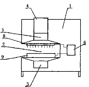
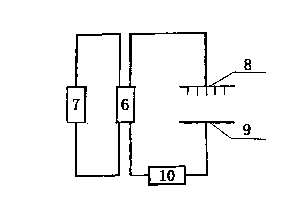
[0022] 3. The upper pole plate is installed on the top of the evaporation chamber, the lower pole plate is installed on the bottom of the evaporation chamber, the upper pole plate is connected to the negative pole of the output end of the voltage regulating rectifier, and the lower pole plate is connected to the positive pole of the output end of the voltage regulating rectifier;
[0023] 4. The distance between the free end of the needle electrode on the upper plate and the lower plate is between 12cm.
Embodiment 2
[0025] Its implementation steps are as follows:
[0026] 1. Upper plate: Rivet the needle electrodes on the copper plate at a distance of 4cm between each needle electrode;
[0027] 2. Lower pole plate: take aluminum material and process it into a mesh plate;
[0028] 3. The upper pole plate is installed on the top of the evaporation chamber, the lower pole plate is installed on the bottom of the evaporation chamber, the upper pole plate is connected to the negative pole of the output end of the voltage regulating rectifier, and the lower pole plate is connected to the positive pole of the output end of the voltage regulating rectifier;
[0029] 4. The distance between the free end of the needle electrode on the upper plate and the lower plate is between 14cm.
Embodiment 3
[0031] Its implementation steps are as follows:
[0032] 1. Upper plate: Fix the needle electrodes on the copper plate with screws at a distance of 4cm between each needle electrode;
[0033] 2. Lower pole plate: take aluminum material and process it into a mesh plate;
[0034] 3. The upper pole plate is installed on the top of the evaporation chamber, the lower pole plate is installed on the bottom of the evaporation chamber, the upper pole plate is connected to the negative pole of the output end of the voltage regulating rectifier, and the lower pole plate is connected to the positive pole of the output end of the voltage regulating rectifier;
[0035] 4. The distance between the free end of the needle electrode on the upper plate and the lower plate is between 16cm.
PUM
| Property | Measurement | Unit |
|---|---|---|
| Thickness | aaaaa | aaaaa |
Abstract
Description
Claims
Application Information