High-energy-storage flywheel rotor and manufacturing method thereof

A technology for energy storage flywheels and manufacturing methods, which is applied in the direction of flywheels, etc., can solve the problems of difficult forming of flywheels and easy layering in the radial direction, and achieve the effects of increasing energy storage density and improving stress distribution

Inactive Publication Date: 2014-06-18
北京奇峰聚能科技有限公司
View PDF5 Cites 12 Cited by
  • Summary
  • Abstract
  • Description
  • Claims
  • Application Information

AI Technical Summary

Problems solved by technology

The hub adopts integral casting, and the rim adopts wet winding molding technology, and solves the problems of large-size compos...

Method used


Image

  • High-energy-storage flywheel rotor and manufacturing method thereof
  • High-energy-storage flywheel rotor and manufacturing method thereof
  • High-energy-storage flywheel rotor and manufacturing method thereof

Examples


Embodiment 1

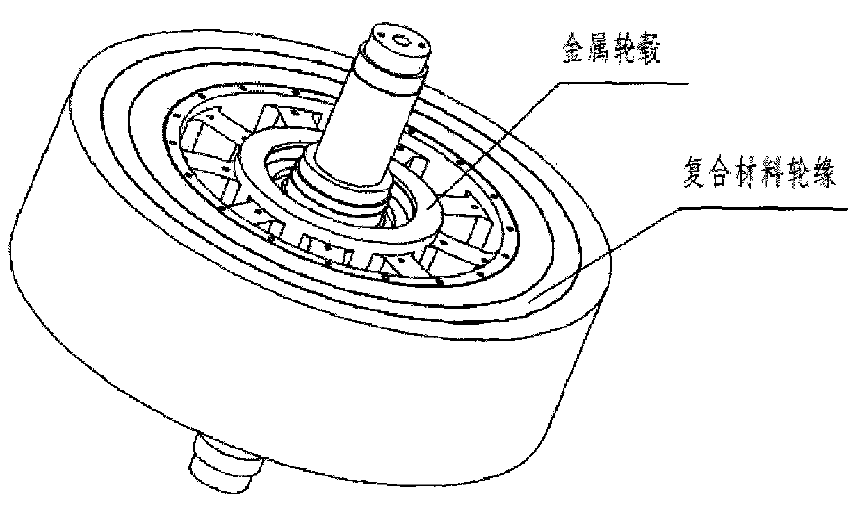
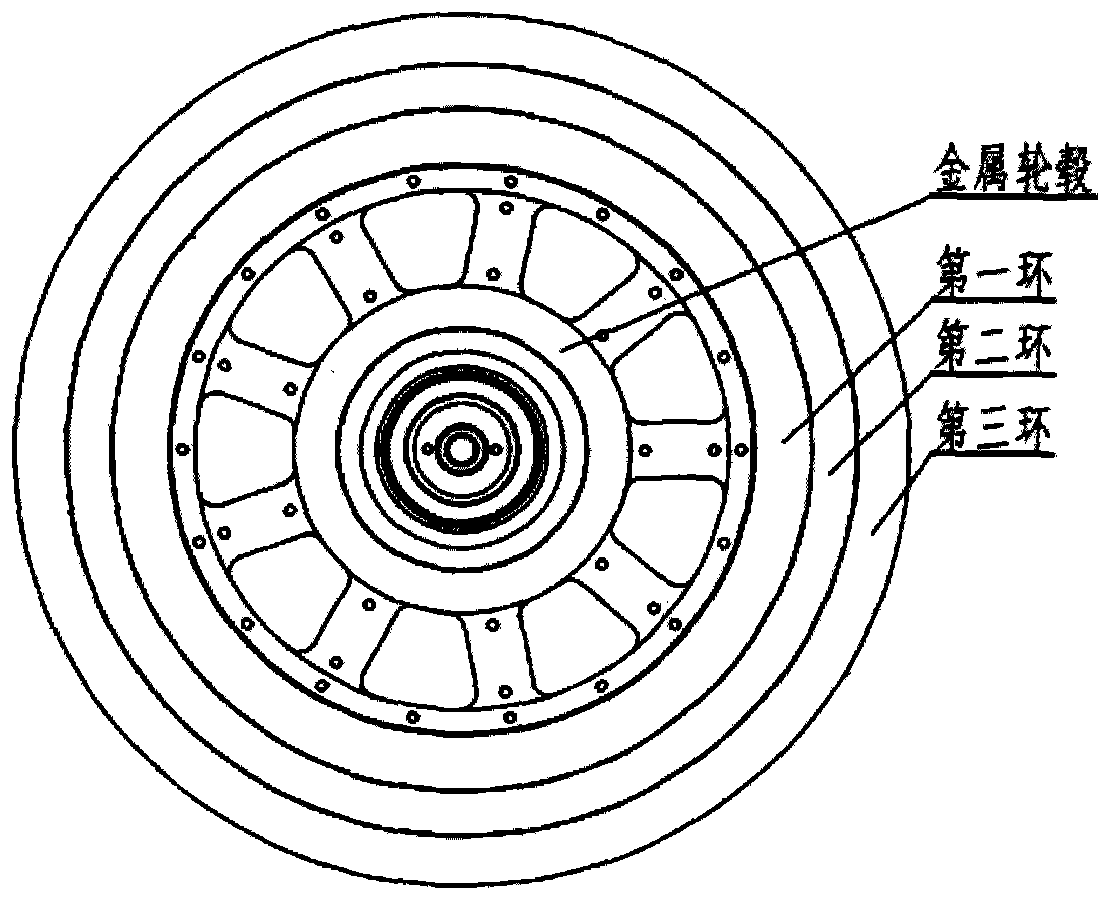
[0027] Such as Figure 1-2 As shown, a large energy storage flywheel rotor includes a metal hub and a rim, the rim is a ring structure of multi-layer carbon fiber reinforced composite material, the surface of the metal hub is wound with glass fiber reinforced composite material, and the multi-layer carbon fiber reinforced The composite ring passes sequentially over the fit-up suit and the metal hub wrapped with glass fiber reinforced composite. Among them, the outer diameter of the metal hub or the inner diameter of the rim is 516mm, the outer diameter of the composite material rim is 786mm, the height is 250mm, and the diameter of the central axis is 100mm.

[0028] According to the ring and radial stress distribution of the rotor rim part obtained by finite element analysis, the rim part is divided into three rings, and the interference is increased between the rings, which changes the radial stress distribution of the flywheel and generates The pre-pressure is ensured, so ...

Embodiment 2

[0031] The manufacturing method of a flywheel rotor involved in the present invention, the hub and the rim are respectively formed by selecting different materials, and then assembled. The forming method of the hub and the rim is as follows:

[0032] The casting method of the hub of the energy storage flywheel comprises the following steps: making wooden molds, sand cores, casting in a closed box, cleaning the casting after being kept warm in the sand box, cutting the riser with gas, completing the casting of the hub of the energy storage flywheel, and then cooling The method of combining thermal processing, the flywheel hub is obtained after the final finishing.

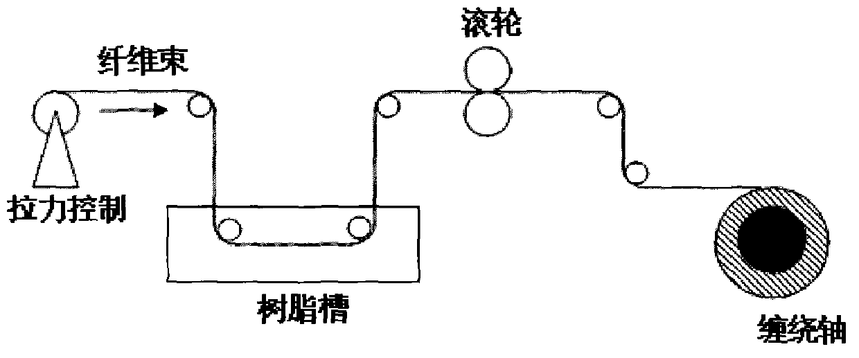
[0033] The rim of the flywheel rotor involved in the present invention consists of three rings of fiber-reinforced composite material, and the forming process of a single ring of fiber-reinforced composite material is as follows:

[0034] The whole process adopts the wet winding process, and the schematic diagram of...


PUM

PropertyMeasurementUnit
Outer diameteraaaaaaaaaa
Diameteraaaaaaaaaa
Thicknessaaaaaaaaaa

Abstract

The invention relates to a high-energy-storage flywheel rotor and a manufacturing method thereof. The flywheel rotor is composed of a metal hub and a composite material rim. The metal hub is made of a high strength alloy steel material and is formed in an inblock cast mode. The rim includes three fiber reinforced composite material rings which sequentially sleeve the hub in an interference assembly mode. The three fiber reinforced composite material rings are formed through a wet method winding process, and a gradation winding curing process and a tension decreasing winding process are adopted in the manufacturing process. By means of the three-layer structure obtained through tension winding and interference fit assembly, the radial stress distribution of a flywheel is changed, prestress is generated among the layers, and the flywheel is not delaminated or loosed even under high rotating speed. The problem that high rotating speed flywheel use cannot be met by metal flywheel strength, low energy storage efficiency and the like is solved, and the flywheel use safety and reliability are greatly improved.

Description

technical field [0001] The invention relates to a large energy storage flywheel rotor and a manufacturing method thereof. technical background [0002] Flywheel energy storage is a new type of high-efficiency mechanical energy storage technology that can convert electric energy, wind energy, solar energy and other energy into the rotational kinetic energy of the flywheel for storage. In the past ten years, with the breakthrough of a series of key technologies such as new high-strength fiber composite materials, electromagnetic suspension bearings and power electronics technology, the superiority of composite flywheel energy storage systems has gradually emerged. Compared with steel flywheels, It has the advantages of high energy storage density, light weight, and long life, making it widely used in many fields such as electric vehicles, aerospace, power grid peak regulation, and uninterruptible power supply backup power. [0003] There are two ways to increase the stored en...

Claims


Application Information

Patent Timeline
IPC IPC(8): F16F15/30B29C70/30
CPCY02E60/16
Inventor 蒋涛刘芝秀李珍裴艳敏孔德群
Owner 北京奇峰聚能科技有限公司
Why Eureka
Try Eureka