Synchrotron radiation in-situ detection device used for electrocatalysis reaction

An in-situ detection and electrocatalysis technology, which is applied in measurement devices, material analysis using wave/particle radiation, and material analysis by electromagnetic means, etc., can solve the problem of difficult to provide real and effective information on the mechanism of catalyst action.

Active Publication Date: 2014-06-25
DALIAN INST OF CHEM PHYSICS CHINESE ACAD OF SCI
View PDF4 Cites 13 Cited by
  • Summary
  • Abstract
  • Description
  • Claims
  • Application Information

AI Technical Summary

Problems solved by technology

In fact, the surface composition and microstructure of the catalyst will change with the reaction atmosphere, temperature and potent...

Method used


Image

  • Synchrotron radiation in-situ detection device used for electrocatalysis reaction
  • Synchrotron radiation in-situ detection device used for electrocatalysis reaction
  • Synchrotron radiation in-situ detection device used for electrocatalysis reaction

Examples


Embodiment 1

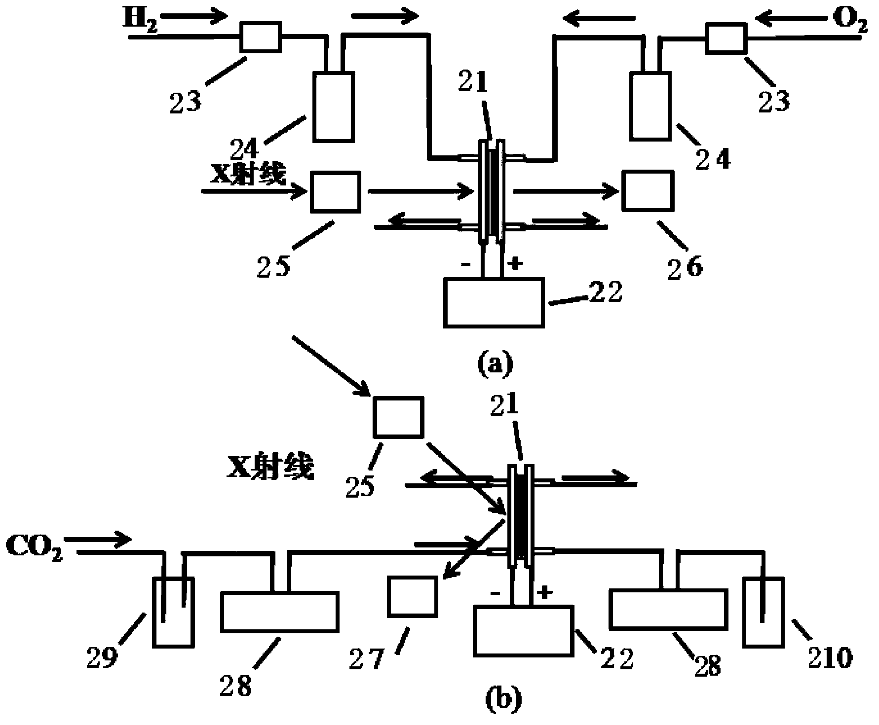
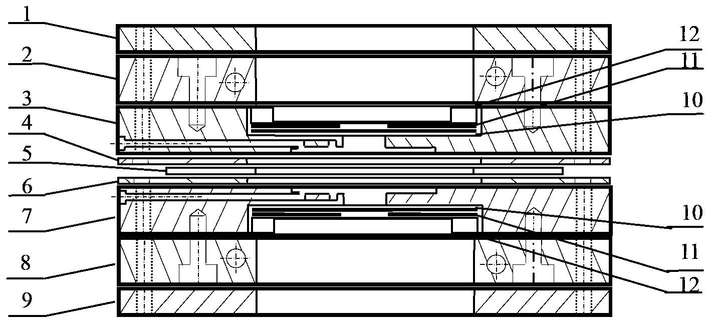
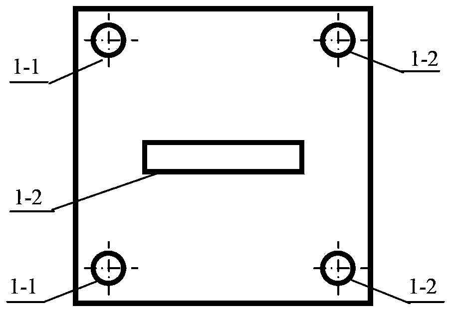
[0045] The X-ray absorption near-edge structure (XANES) spectrum of the cathode PtFe / C catalyst was tested under the working conditions of the proton exchange membrane fuel cell. The electrode was prepared by brush coating method, and then the anode and cathode were placed on both sides of the electrolyte membrane, and the membrane electrode was obtained by hot pressing at 135°C for 3 minutes, wherein the anode was a Pt / C catalyst, and the cathode was a PtFe / C catalyst prepared by an impregnation method. C catalyst, the electrolyte membrane is Naton212. The in-situ cell in the transmission mode is used to detect the signal of iron in the membrane electrode. The assembly process of the in-situ cell is as follows: a serpentine flow field with a width of 1 mm is processed on the side of the anode and cathode flow field plates, and a diameter of 1 mm is processed in the middle of the flow field plate. 2mm round hole. Process a rectangular groove with a size of 1cm×4cm on the othe...

Embodiment 2

[0047] Test XANES spectrum of Fe / C catalyst in carbon dioxide electrolysis cell cathode. The membrane electrode was prepared by the same process as in Example 1, wherein the cathode catalyst was Fe / C catalyst prepared by impregnation method, the anode catalyst was platinum black catalyst, and the electrolyte membrane was sodium Naton117. The in situ cell in fluorescence mode was used to detect the iron signal in the membrane electrode, and the assembly process of the in situ cell was the same as that in Example 1. The anode and cathode of the in-situ cell are respectively fed with NaOH solution with a concentration of 0.5mol / L and NaHCO saturated with carbon dioxide. 3 Solution (concentration is 0.5mol / L), use the heating rod to heat the in-situ cell to 40°C, test the current-voltage curve of the membrane electrode through the potentiostat, and use the circular hole detection window in the middle of the in-situ cell to detect the cathode catalyst Fe From the XANES spectrum, i...


PUM


Abstract

The invention discloses a synchrotron radiation in-situ detection device used for electrocatalysis reaction. The synchrotron radiation in-situ detection device comprises a synchrotron radiation X ray absorption fine structure (XAFS) line station front ionization chamber, a synchrotron radiation XAFS line station back ionization chamber (or a fluorescence detector) and an in-situ pool. A membrane electrode for electrocatalysis reaction is arranged in the in-situ pool, and in the condition that detection windows of components of the in-situ pool are in the same center line, X-ray irradiates onto the membrane electrode, and then reaches, in a transmission or reflection way, to the synchrotron radiation XAFS line station back ionization chamber or the fluorescence detector so as to achieve in-situ detection of the catalyst structure in the electrocatalysis reaction process; the detection windows of the in-situ pool are in the center of a flow field plate, the dead volume is less, the accuracy and reliability of experimental data can be improved, a heating plate and the flow field plate in the in-situ pool are fixed together by bolts, the detection windows on the flow field plate are sealed, and the assembly and replacement of the membrane electrode are facilitated. The synchrotron radiation in-situ detection device is a set of detection device suitable for the study of the electrocatalytic reaction process and mechanism.

Description

technical field [0001] The invention relates to a synchrotron radiation in-situ detection device for electrocatalytic reaction, in particular to a synchrotron radiation in-situ detection device for a proton exchange membrane fuel cell and a carbon dioxide electrolysis cell. Background technique [0002] Catalysts are key materials in electrocatalytic reactions, and their composition and structure directly affect electrocatalytic activity and efficiency. During the electrocatalytic reaction, researchers usually use a potentiostat to obtain current-voltage or AC impedance data to evaluate the activity of the catalyst, and then combine offline X-ray diffraction, X-ray photoelectron spectroscopy and other techniques to characterize the structure and surface of the catalyst. composition to study the structure-activity relationship of the catalyst. In fact, the surface composition and microstructure of the catalyst will change with the reaction atmosphere, temperature and potenti...

Claims


Application Information

Patent Timeline
IPC IPC(8): G01N23/223G01N27/62
Inventor 汪国雄于良邓德会谭大力潘秀莲包信和
Owner DALIAN INST OF CHEM PHYSICS CHINESE ACAD OF SCI
Why Eureka
Try Eureka