Packaging structure of distributed feedback fiber laser

A fiber laser and packaging structure technology, applied to the structure/shape of the active medium, laser components, etc., to achieve the effects of compact overall structure, favorable integration, and reduced response sensitivity

Active Publication Date: 2014-06-25
山东飞博赛斯光电科技有限公司
View PDF5 Cites 17 Cited by
  • Summary
  • Abstract
  • Description
  • Claims
  • Application Information

AI Technical Summary

Problems solved by technology

Patent CN102035125.A designed a distributed feedback fiber laser packaging structure using sound insulation boards and steel wire rope shock absorbers, which can realize the functions of sound insulation, vibration isolation, temperature control and high frequency modulation, but i

Method used


Image

  • Packaging structure of distributed feedback fiber laser
  • Packaging structure of distributed feedback fiber laser

Examples


Embodiment 1

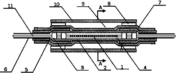
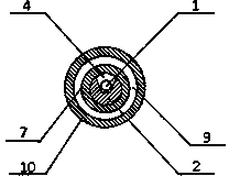
[0016] Embodiment 1: as figure 1 As shown, a packaging structure of an active phase-shifting fiber grating, which includes a quartz U-shaped groove 2 and silicone grease or silicone oil 4 filled in the quartz U-shaped groove 2, the active phase-shifting fiber grating 1 is immersed in the quartz U-shaped In the silicone grease or silicone oil 4 in the groove 2, the grating pigtails 11 at both ends of the active phase-shifting fiber grating 1 are bonded and fixed to the quartz U-shaped groove 2 through two parallel thermosetting adhesives 3 to make the active phase-shifting fiber grating 1 Keep a free state without bearing axial stress; the grating pigtails 11 located outside the quartz U-shaped groove 2 are respectively covered with plastic sleeves 6, and the two ends of the quartz U-shaped groove 2 together with the plastic sleeves 6 on both sides are inserted respectively Into the corresponding heat-melt tube 5, the two-section heat-melt tube 5 and the quartz U-shaped groove ...

Embodiment 3

[0021] Embodiment 3: The similarities between this embodiment and Embodiment 2 will not be repeated, and the difference is that the active phase-shifting fiber grating 1 is an 8cm long ytterbium-doped fiber grating, and the line width jumps in the range of 20-500kHz in a 60dB noise environment. Change, the relative intensity noise is up to -65dB. After the bare fiber is coated, the metal sleeve 10 made of a 10cm long quartz U-shaped groove 2 and a 10cm long copper tube is packaged according to the same steps. The semi-fluid in the tank 2 adopts thermal conductive silicone grease 4 . The linewidth of the packaged Ytterbium-doped distributed feedback fiber laser is basically stable at about 30kHz, and the relative intensity noise is kept below -80dB.


PUM

PropertyMeasurementUnit
Gate lengthaaaaaaaaaa
Diameteraaaaaaaaaa

Abstract

The invention discloses a packaging structure of a distributed feedback fiber laser. The packaging structure is characterized by comprising a quartz U-shaped groove and silicone grease or silicone oil with which the quartz U-shaped groove is filled, an active phase shift fiber bragg grating is immersed in the silicone grease or silicone oil in the quartz U-shaped groove, tail fibers at the two ends of the active phase shift fiber bragg grating are fixedly bonded to the quartz U-shaped groove through two pieces of parallel thermocuring glue respectively to enable the active phase shift fiber bragg grating to be kept in the free state under the condition that axial stress is not borne, the grating tail fibers located outside the quartz U-shaped groove are sleeved with plastic sleeves respectively, the two ends of the quartz U-shaped groove and the plastic sleeves on the two sides are jointly inserted into corresponding hot melting pipes respectively, the two hot melting pipes and the quartz U-shaped groove are integrally inserted into a heat shrink pipe, the two hot melting pipes and the heat shrink pipe are heated to be shrunk to enable the two plastic sleeves and the quartz U-shaped groove to be connected into a whole, and meanwhile the heat shrink pipe is shrunk to enable the silicone grease or silicone oil to be sealed in the quartz U-shaped groove.

Description

technical field [0001] The invention relates to a packaging of a distributed feedback fiber laser gain medium and a resonant cavity, in particular to an active phase-shifting fiber grating packaging structure. Background technique [0002] Distributed feedback fiber laser is a typical narrow-linewidth fiber laser. It uses a single active phase-shifting fiber grating as the laser resonator and gain medium. It has extremely narrow linewidth, extremely low noise and stable single longitudinal mode. advantages such as operation. Due to the slender structure and single-frequency output characteristics of the distributed feedback fiber laser, it is extremely sensitive to environmental noise such as external vibration and sound. Weak sound waves or vibrations will cause obvious changes in frequency and phase, so it is often Used as fiber optic hydrophones and microseismic sensors. When used as a laser light source, the distributed feedback fiber laser without isolation protection...

Claims


Application Information

Patent Timeline
IPC IPC(8): H01S3/067H01S3/02
Inventor 宋志强王昌祁海峰倪家升郭健
Owner 山东飞博赛斯光电科技有限公司
Why Eureka
Try Eureka