Single-welding bend pressing and molding method

A press forming and elbow technology, which is applied in the field of press forming, can solve the problems of complicated process and waste of energy, and achieve the effects of simple process, reduced product cost and high material utilization rate

Active Publication Date: 2014-07-02
YANSHAN UNIV
View PDF8 Cites 15 Cited by
  • Summary
  • Abstract
  • Description
  • Claims
  • Application Information

AI Technical Summary

Problems solved by technology

However, a special horizontal elbow push bending machine and a special mold are required, and the process is relatively complicated
In addition, the blank needs to be heated, which wastes energy

Method used


Image

  • Single-welding bend pressing and molding method
  • Single-welding bend pressing and molding method
  • Single-welding bend pressing and molding method

Examples


Embodiment 1

[0041] The present invention is described by taking a 90-degree elbow of production material Q235, wall thickness t=2.5mm, nominal diameter D=100mm, and bending radius 1.25D=125mm as an example.

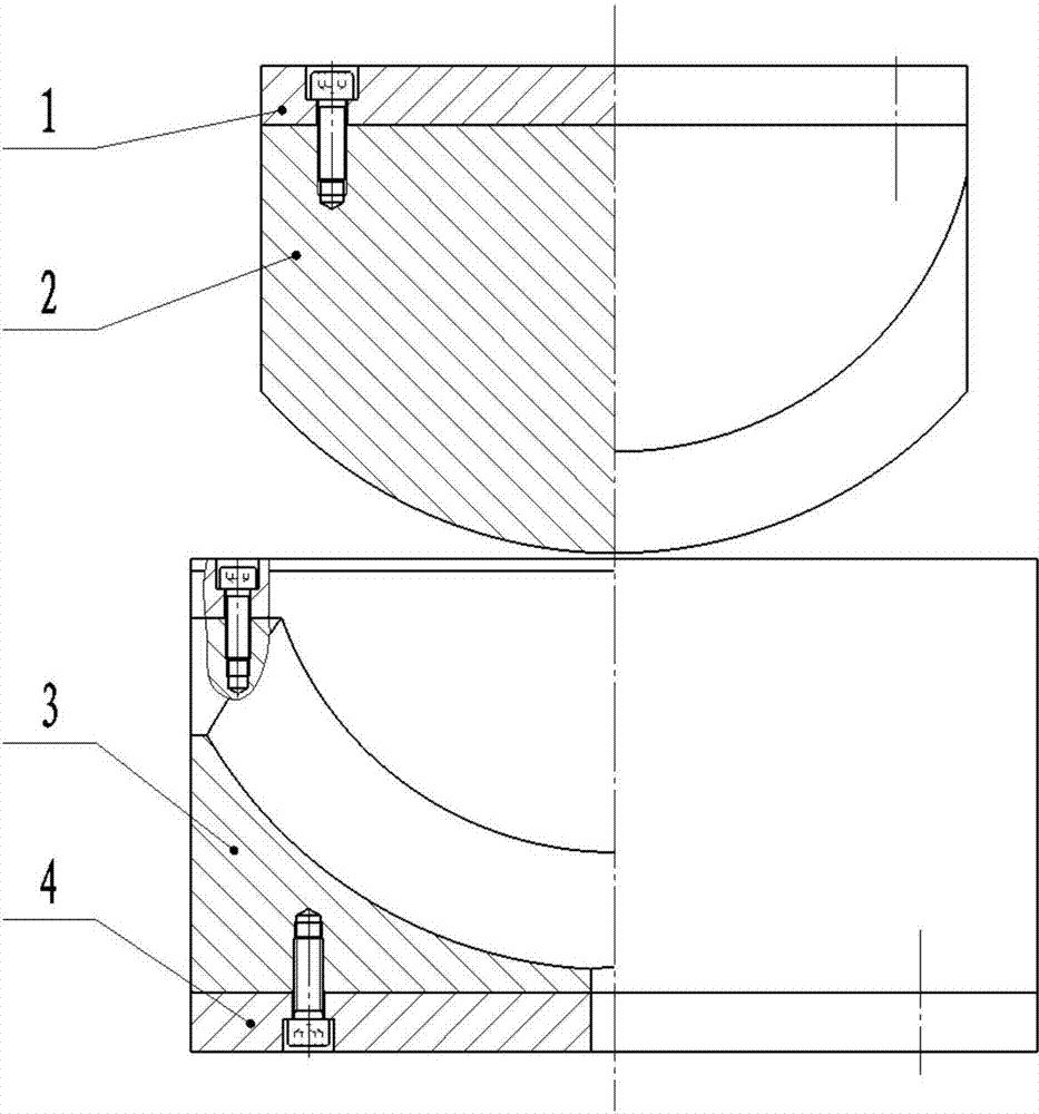
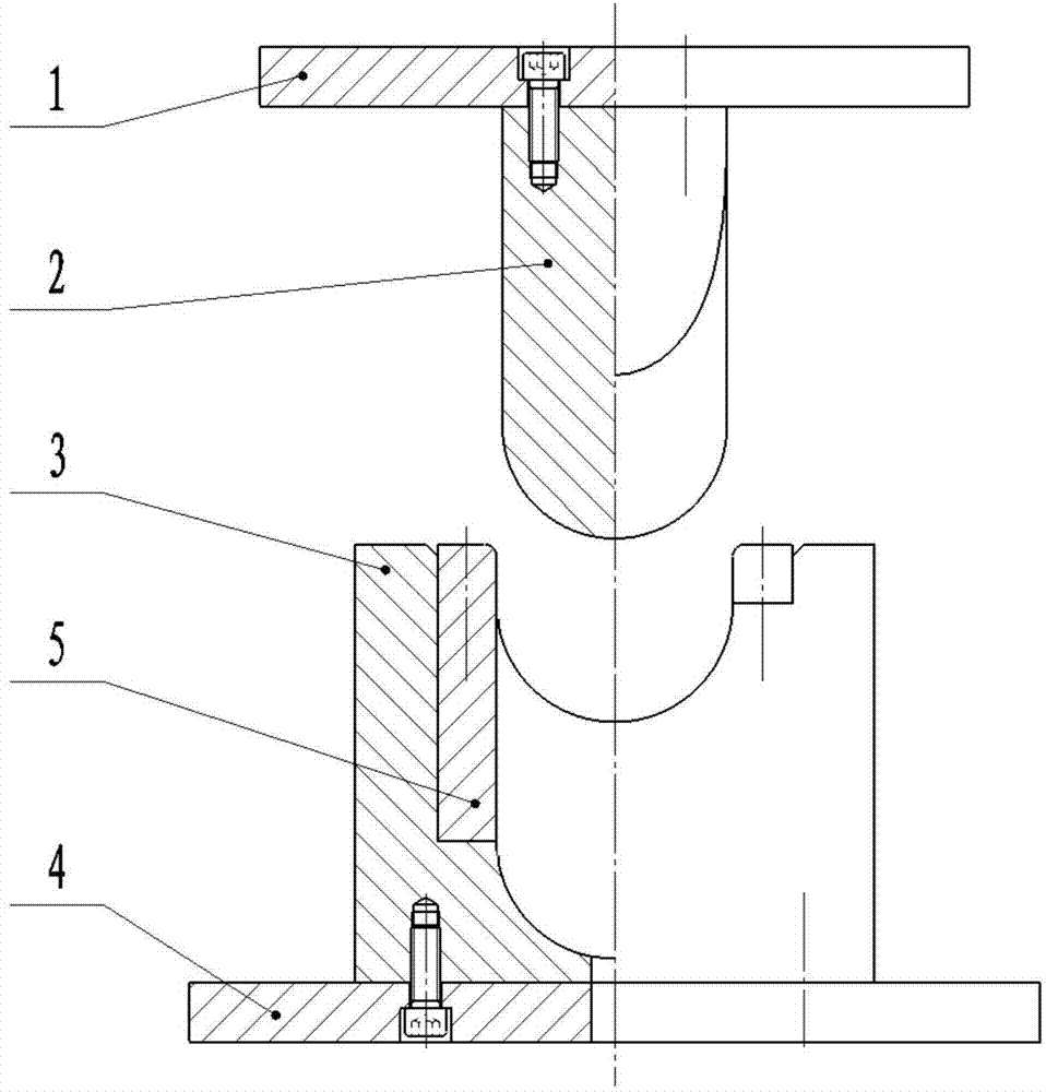
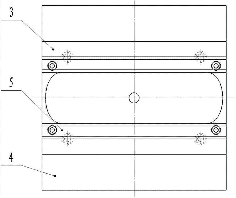
[0042] Select a Q235 plate with a thickness of 2.5mm as the raw material, and the shape and size of the blank 7 are calculated by the Dynaform software plate size (such as Figure 7 shown), and cut with a cutting machine. Install the finished blank on the machine tool, and process the groove required by the cross-section on both sides of the blank through the relative movement of the tool and the blank (such as Figure 8 Shown), the groove is a Y-shaped groove, and the size is 1×1.5mm. Place the blank on the die with the groove facing down, and position it through the positioning pins so that the centerline of the blank is aligned with the centerline of the die (such as Figure 9 shown). The die is fixed on the workbench of the press, and the punch I is installed on the slider of ...

Embodiment 2

[0044] The present invention will be described by taking a 90-degree elbow with production material X80, wall thickness t=30mm, nominal diameter D=1200mm, and bending radius 1.5D=1800mm as an example.

[0045] The thickness is 30mm X80 plate is selected as the raw material, the shape and size of the blank is calculated by the Dynaform software plate size, and the material is cut with a cutting machine. The finished blank is clamped on the machine tool, and the groove required by the cross section on both sides of the blank is processed through the relative movement of the tool and the blank. The groove is a Y-shaped groove with a size of 12×18mm. Place the blank on the die with the groove facing down, and position it through the positioning pins so that the centerline of the blank is aligned with the centerline of the die. The die is fixed on the workbench of the press, and the punch I is installed on the slider of the press, and the slider drives the punch I to press down to ...


PUM

PropertyMeasurementUnit
Wall thicknessaaaaaaaaaa
Nominal diameteraaaaaaaaaa
Bending radiusaaaaaaaaaa

Abstract

The invention relates to a single-welding bend pressing and molding method. The method comprises the main steps: selecting slabs as thick as the bend wall as raw materials, unfolding the bend by DYNAFORM software to obtain the size of the slab and blanking with a cutter; processing undercuts on both concave sides of the slab; pressing the cross section of the slab to be U-shaped; pressing the slab with the U-shaped cross section to be slab with an O-shaped cross section; welding an inner-arc opening of the slab with O-shaped cross section; and cutting the redundant slab at both ends of the bend and machining both ends according to the requirement to obtain a qualified bend part. Dies for pressing U-shaped cross section and O-shaped cross section comprise a concave die, a convex die I and a convex die II, and the top surface of the convex die I is a plane; the lower part is in a U-shaped structure; the top surface of convex the die II is a plane; both sides perpendicular to the plane are part sector; the arc-shaped surface on the lower part of the convex die II is provided with a groove corresponding to the machined bend surface. The prepared product is few in welding line and high in quality, the dies are simple, core rods are not needed, energy consumption is low as heat is not needed, the process is simple and production efficiency is high.

Description

technical field [0001] The invention relates to a compression molding method, in particular to a compression molding method for large-diameter single-weld elbows. Background technique [0002] Elbows are widely used in modern industry, and can be seen in petroleum, natural gas, chemical industry, electrical engineering and textile. Its forming methods mainly include stamping-butt welding, hot pushing, cold pushing, simmering, extrusion and pressing. [0003] The advantages of stamping-butt welding elbow are simple mold structure, convenient and flexible use, low mold cost, and no special hydraulic equipment (you can make full use of the existing hydraulic machine), small investment cost, and wide processing range, but The inner arc and outer arc of the formed elbow will respectively leave a weld seam, which will reduce the mechanical properties of the elbow. [0004] The elbow processed by the hot push forming process has a uniform wall thickness and a smooth appearance, a...

Claims


Application Information

Patent Timeline
IPC IPC(8): B21C37/28B21D37/10
Inventor 赵军于高潮王春鸽
Owner YANSHAN UNIV
Why Eureka
Try Eureka