
Double buffer relief valve

A technology of overflow valve and double buffer, which is applied to engine components, fuel injection pumps, machines/engines, etc., can solve the problems of reduced control accuracy of fuel intake, increased gradient of fuel pressure drop, and shortened life of system components. Achieve the effect of improving reliability, reducing pressure drop gradient, and reducing oil drainage rate

Active Publication Date: 2016-05-04
HARBIN ENG UNIV
View PDF6 Cites 0 Cited by
  • Summary
  • Abstract
  • Description
  • Claims
  • Application Information

AI Technical Summary

Problems solved by technology

The fuel delivery pressure is controlled by installing a relief valve between the fuel delivery pump and the high-pressure pump. However, when the ordinary relief valve is opened, due to the large oil discharge rate, it is easy to cause the gradient of the fuel pressure drop to increase, resulting in the pressure of the fuel entering the high-pressure fuel pump. If the fluctuation is large, the control accuracy of the oil intake will be reduced, which will lead to a significant increase in the fluctuation of the rail pressure, which will directly affect the stability of the diesel engine.
When the oil inlet pressure fluctuates greatly, the fuel entering the pump chamber will contain air bubbles, and the air bubbles will burst after the fuel is compressed, causing serious cavitation in the plunger chamber, high-pressure oil pipe and common rail pipe, resulting in the life of the system components reduce

Method used


Image

  • Double buffer relief valve
  • Double buffer relief valve
  • Double buffer relief valve

Examples


Embodiment Construction

[0015] The present invention is described in more detail below in conjunction with accompanying drawing example:

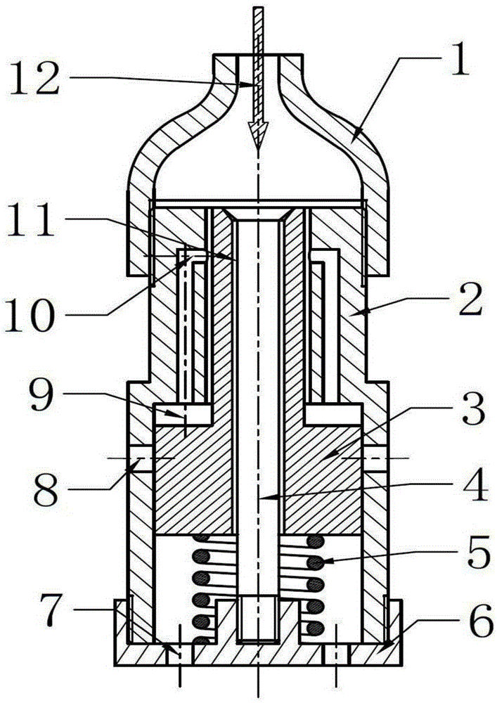
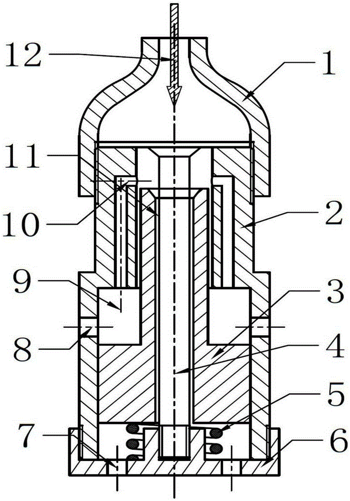
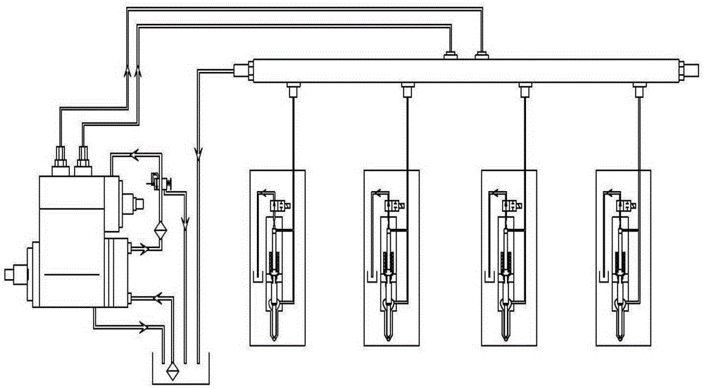
[0016] combine Figure 1~3 , the main structural components of the present invention include: oil inlet housing 1, overflow valve body 2, moving piston 3, fixed valve stem 4, return spring 5, base 6, discharge hole 7, discharge hole 8, variable volume chamber 9. Throttle hole 10, throttle oil passage 11 and oil inlet 12. The oil inlet housing 1 is installed on the upper end of the overflow valve, and the oil inlet on the oil inlet housing and the upper end surface of the overflow valve form a fixed volume chamber. The moving piston 3 adopts a variable cross-section piston, which is installed in the overflow valve body. The lower end surface of the moving piston 3 is supported by a return spring 5. The moving piston 3 is a hollow piston. On the one hand, a fixed valve stem 4 needs to be installed in the center of the moving piston 3. The moving mass of the moving...


PUM


Abstract

The invention aims to provide a double buffering type overflow valve which comprises an oil inlet shell, an overflow valve body, a movable piston, a fixed valve rod, a reset spring, a base, a throttling oilway and an oil inlet. The movable piston and the fixed valve rod form the first-stage buffering throttling oilway. The throttling hole of the valve body form a second-stage buffering oilway. The throttling oilway and the throttling hole jointly form a two-stage buffering oilway. The double buffering type overflow valve has the advantages that fuel oil discharge is performed in a two-stage buffering manner, fuel oil discharge speed is reduced, fuel oil pressure drop gradient is lowered, stable fuel oil transfer pressure in a system is kept, control precision of fuel oil inlet amount is increased, stable rail pressure in a common rail pipe is kept, same oil spraying amount of different cylinders in each circulation is guaranteed, matching consistency of a fuel oil system and a diesel engine is increased, fuel oil mixed with bubbles can be prevented from entering a high-pressure oilway, cavitation erosion, caused by bubble crack, in a high-pressure oil pipe, the common rail pipe and an oil sprayer, and reliability of a fuel oil spraying system is increased.

Description

technical field [0001] The invention relates to an engine fuel injection device, in particular to a device for maintaining stable pressure in an oil circuit. Background technique [0002] With the increasing environmental pollution, it is imminent to improve the emission performance of diesel engines. The electronic control of diesel engines has become an important measure to solve the emission problems of diesel engines in the future. The electronically controlled high-pressure common rail fuel injection system has the characteristics of high injection pressure, flexible and controllable fuel injection volume, fuel injection timing and fuel injection law, which can significantly improve fuel efficiency. The quality of atomization can improve the economic performance and emission performance of diesel engines, while reducing harmful substances in emissions. It is currently widely used in automobiles and marine diesel engines. Maintaining the stability of the fuel pressure i...

Claims


Application Information

Patent Timeline
Patent Type & Authority Patents(China)
IPC IPC(8): F02M59/46F02M59/34
Inventor 范立云陈超王作群张建宇扈爽董全马修真宋恩哲石勇
Owner HARBIN ENG UNIV
Learn More