

Cleaning technology of generator rotor water cooling system
A generator rotor and water cooling system technology, applied in the field of cleaning technology, can solve problems such as energy loss, affecting cooling effect, and corrosion of hollow copper wires, so as to reduce operating temperature and temperature difference, improve wire heat exchange efficiency, and restore water flow capacity Effect
- Summary
- Abstract
- Description
- Claims
- Application Information
AI Technical Summary
Problems solved by technology
Method used
Image

Examples
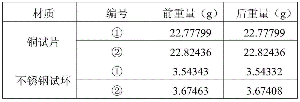
Embodiment 1
[0030] Take the coal-fired generator set QFS2-330-2 generator as an example:
[0031]Its cooling system is a double water cooling system, and the rotor winding of the double water internal cooling cooling method is water internal cooling. The factory test pressure of the internal cooling water system of the stator and rotor windings is 1MPa; the water pressure after installation is 0.75MPa.
[0032] 1.1 Cleaning process:
[0033] A cleaning process for the water-cooling system of the generator rotor. The water-cooling system of the generator rotor is cleaned in a forward and reverse cycle, and sequentially undergoes the washing process before preheating, system preheating, alkali washing, water washing after alkali washing, pre-slow release, pickling, The process of water washing after pickling, pre-filming, and water washing after pre-filming completes the cleaning of the water cooling system of the generator rotor.
[0034] Among them, the generator rotor water cooling sys...
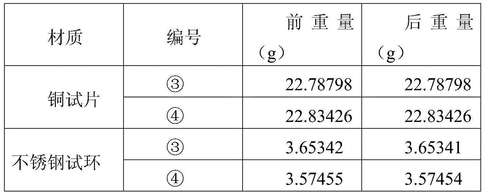
Embodiment 2
[0068] Take the coal-fired generator set QFS2-330-2 generator as an example:
[0069] Its cooling system is a double water cooling system, and the rotor winding of the double water internal cooling cooling method is water internal cooling. The factory test pressure of the internal cooling water system of the stator and rotor windings is 1MPa; the water pressure after installation is 0.75MPa.
[0070] 2.1 Cleaning process:
[0071] A cleaning process for the water-cooling system of the generator rotor. The water-cooling system of the generator rotor is cleaned in a forward and reverse cycle, and sequentially undergoes the washing process before preheating, system preheating, alkali washing, water washing after alkali washing, pre-slow release, pickling, The process of water washing after pickling, pre-filming, and water washing after pre-filming completes the cleaning of the water cooling system of the generator rotor.
[0072] Among them, the generator rotor water cooling sy...
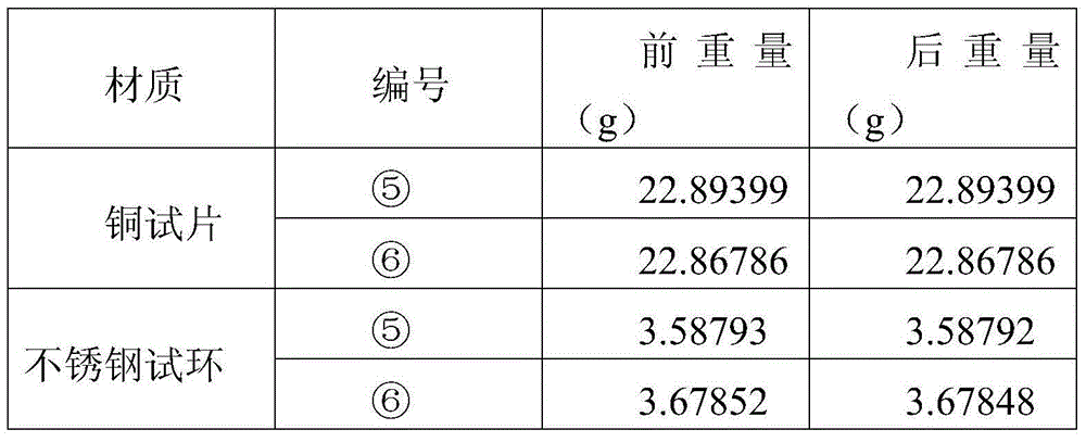
Embodiment 3
[0101] Take the coal-fired generator set QFS2-330-2 generator as an example:
[0102] Its cooling system is a double water cooling system, and the rotor winding of the double water internal cooling cooling method is water internal cooling. The factory test pressure of the internal cooling water system of the stator and rotor windings is 1MPa; the water pressure after installation is 0.75MPa.
[0103] 3.1 Cleaning process:
[0104] A cleaning process for the water-cooling system of the generator rotor. The water-cooling system of the generator rotor is cleaned in a forward and reverse cycle, and then undergoes system preheating, alkali cleaning, water washing after alkali cleaning, pre-sustained release, pickling, water washing after pickling, and pre-slow release. The process of water washing after film and pre-film completes the cleaning of the water cooling system of the generator rotor.
[0105] Among them, the generator rotor water cooling system includes the cooling wat...
PUM
 Abstract
Description
Claims
Application Information