Driving circuit with electronic differential function and application of driving circuit

A drive circuit, electronic differential technology, applied in electric vehicles, control drive, transportation and packaging, etc., can solve problems such as lack of low-battery automatic alarm operation management mechanism, total battery voltage can not be used, vehicle breakdown, etc.

Active Publication Date: 2014-07-16
佛山陀普科技有限公司
View PDF4 Cites 5 Cited by
  • Summary
  • Abstract
  • Description
  • Claims
  • Application Information

AI Technical Summary

Problems solved by technology

[0006] (2) Evaluate the state of charge of the battery pack based on the total voltage of the battery pack, which basically meets the requirements of lead-acid batteries; the correlation between the state of charge of lithium-ion batteries and its total voltage is far lower than that of lead-acid batteries, and the total voltage of the battery pack It cannot be used as the basis for evaluating the state of charge of lithium-ion battery packs, and the existing system only meets the evaluation of the state of charge of lead-acid battery packs, and does not have the function of real-time online measurement and evaluation of the state of charge of lithium-ion battery packs
[0007] (3) Lack of automatic low-battery warning and operation management mechanism that automatically limits the output of the motor, which may easily cause the vehicle to break down in the middle of operation, and forced protection will lead to power output restrictions and other events that affect driving safety.

Method used


Image

  • Driving circuit with electronic differential function and application of driving circuit
  • Driving circuit with electronic differential function and application of driving circuit
  • Driving circuit with electronic differential function and application of driving circuit

Examples


Embodiment 1

[0065] Embodiment 1: Applied to the drive control system of light electric vehicles

[0066]The light electric vehicle has a design speed of 60km / h and uses an asynchronous AC motor with a rated power of 7.5W. The power battery pack uses 24 120AH lithium iron phosphate batteries connected in series with a rated voltage of 72V. According to the characteristics of lithium iron phosphate battery, the battery high voltage protection voltage (charging protection and energy feedback protection voltage) is set to 3.8V, the low voltage protection voltage is set to 2.5V, and the low battery warning voltage is set to 2.8V.

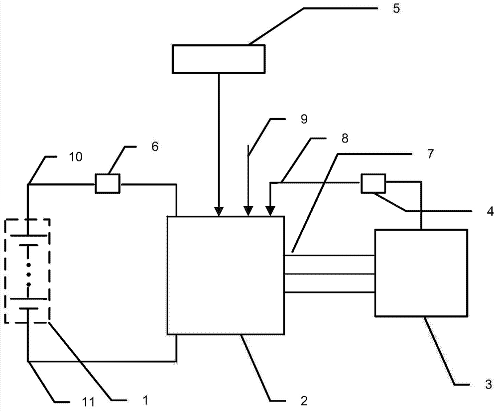
[0067] Such as figure 2 As shown: the light electric vehicle power system includes a power battery pack 1, a motor controller 2 and a motor 3; the motor controller 2 is connected to the motor 3 through the motor three-phase power line 7 and the motor control signal line 9 respectively; The motor speed signal line 8 is connected to the speed sensor 4; the motor con...


PUM


Abstract

The invention discloses a driving circuit with an electronic differential function and application of the driving circuit. The driving circuit comprises an upper-end control bridge circuit and a lower-end control bridge circuit. A base electrode of a first triode of the upper-end control bridge circuit is connected with a master control chip by a first resistor, an emitting electrode of the first triode is connected with an external chip by a tenth resistor, and a collecting electrode of the first triode is connected with a second diode by a second resistor; a base electrode of a second triode is directly connected with the collecting electrode of the first triode, and an emitting electrode of the second triode is respectively directly connected with a second capacitor, a negative electrode of the second diode and the second resistor. The driving circuit with the electronic differential function can be applied to a motor controller, and both the driving circuit with the electronic differential function and a control signal output interface circuit of a motor are connected with the motor. The driving circuit and the application have the advantages that the motor controller has electronic differential and electric quantity evaluating functions, accordingly, the reliability and the efficiency of a system can be improved, and the production cost of equipment can be reduced.

Description

technical field [0001] The invention relates to a drive circuit, in particular to a drive circuit with electronic differential function and its application. The drive circuit is mainly used in electric vehicle motor control systems, especially in electric vehicle motor control systems with electronic differential and power evaluation functions. Background technique [0002] In recent years, the global energy crisis has begun to intensify, and traditional petrochemical energy sources are becoming increasingly exhausted. The environmental problems caused by this, such as air pollution, global temperature rise, and urban dust pollution, are becoming more and more harmful. After the 21st century, governments of various countries and major automobile manufacturers have reached a consensus that energy saving and emission reduction will be the main direction of future automobile technology development. The new energy vehicle has attracted widespread attention from all over the wor...

Claims


Application Information

Patent Timeline
Patent Type & Authority Applications(China)
IPC IPC(8): B60L15/00
Inventor 李慧琪欧阳剑周远山
Owner 佛山陀普科技有限公司
Why Eureka
Try Eureka