High spatial resolution biaxial differential confocal spectrum microscopic imaging method and apparatus

A dual-axis differential confocal and high spatial resolution technology, applied in the field of spectral measurement, can solve the problems of low collection efficiency, unfavorable light source intensity fluctuation suppression, insufficient spatial resolution, etc., to improve sensitivity, improve anti-interference ability, improve The effect of lateral resolution

Active Publication Date: 2014-07-16
BEIJING INSTITUTE OF TECHNOLOGYGY
View PDF5 Cites 17 Cited by
  • Summary
  • Abstract
  • Description
  • Claims
  • Application Information

AI Technical Summary

Problems solved by technology

[0009] The purpose of the present invention is to overcome the defects of low collection efficiency, insufficient spatial resolution, and unfavorable suppression of factors such as ambient background light and light source intensity fluctuations in existing confocal Raman detection instruments, and propose a high spatial resolution Dual-axis differential confocal spectrum detection method and device

Method used


Image

  • High spatial resolution biaxial differential confocal spectrum microscopic imaging method and apparatus
  • High spatial resolution biaxial differential confocal spectrum microscopic imaging method and apparatus
  • High spatial resolution biaxial differential confocal spectrum microscopic imaging method and apparatus

Examples


Embodiment 1

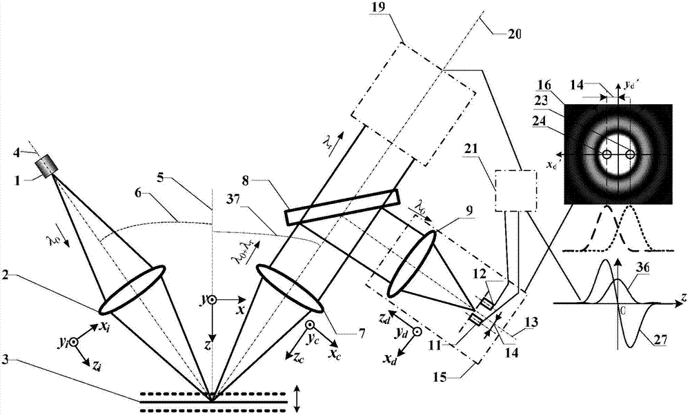
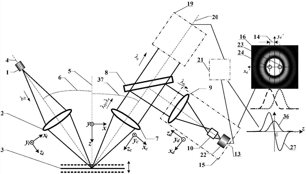
[0049] In this embodiment, the light source 1 is a laser, the polarization modulation device 29 is a radially polarized light generator, the dichroic light splitting system 8 is a Notch filter, the data processing system 21 is a computer, and the first detector 22 is a first CCD detector , the second detector 35 is a second CCD detector.

[0050] Such as figure 2 , image 3 and Figure 6 As shown, the illumination objective lens 2 and the collection objective lens 7 are symmetrically distributed on both sides of the normal line 5 of the measurement surface, and the included angle between the illumination optical axis 4 and the normal line 5 of the measurement surface is θ 1 6. The angle between the collection optical axis 20 and the normal line 5 of the measurement surface is θ 2 37, where θ 1 = θ 2 , taking the 5 directions of the normal line of the measuring surface as the measuring axis, establishing a system coordinate system (x, y, z), a high spatial resolution dual...

Embodiment 2

[0065] In this embodiment, the polarization modulation system 29 is a radially polarized light generator, the dichroic spectroscopic system 8 is a Notch filter, the first detection system 11 is a first point detector, the second detection system 12 is a second point detector, and the data The processing system 21 is a computer, the first detector 22 is a first CCD detector, and the second detector 35 is a second CCD detector.

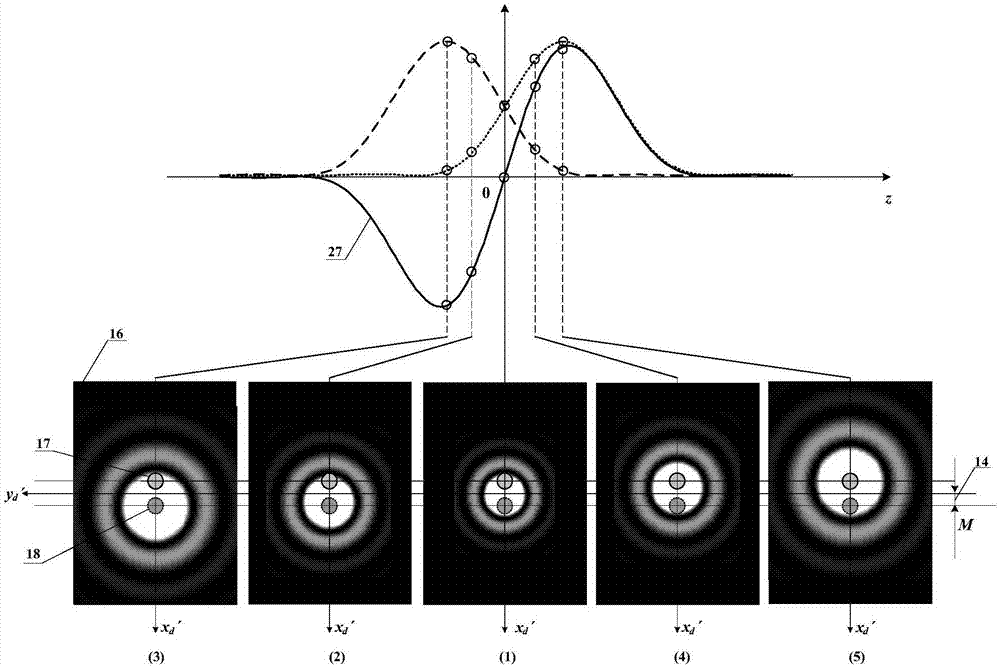
[0066] Such as figure 1 , Figure 4 , Figure 5 and Figure 7 As shown, the embodiment 1 Figure 6 Replace the first CCD detector in the Figure 7 Two point detectors with the same parameters, namely the first point detector 11 and the second point detector 12, can constitute the second embodiment. The positions of the first point detector 11 and the second point detector 12 correspond to the positions of the first virtual pinhole 24 and the second virtual pinhole 23 in Embodiment 1, respectively. The positions of the first virtual pinhole 24 and ...


PUM


Abstract

The invention belongs to the technical field of spectrum measurement, and relates to a high spatial resolution biaxial differential confocal spectrum imaging method and an apparatus. According to the present invention, the biaxial differential confocal microscopy technology and the spectrum detection technology are fused, focal spot cutting differential detection is adopted so as to achieve precise imaging of the geometry position, simplify the optical path structure of the traditional differential confocal microscopy system, inherit the advantages of large visual field and large work distance of the biaxial microscopy technology, and achieve high spatial resolution spectrum integrated detection of the system; and high spatial resolution is provided, three modes such as three-dimensional tomography geometry imaging, spectrum detection and micro-region spectrum tomography imaging are provided, a new solving approach is provided for micro-region spectrum detection, and broad application prospects are provided in the fields of biomedicine, physical material science and the like.

Description

technical field [0001] The invention belongs to the technical field of spectrum measurement, and relates to a high spatial resolution dual-axis differential confocal atlas microscopic imaging method and device, which can be used for three-dimensional shape reconstruction and micro-region spectral detection of various samples. technical background [0002] Since 1990, when G.J.Puppels et al. reported their invention of confocal Raman spectroscopy microscopy in Nature and successfully used it to observe the morphology and composition of single cells and chromosomes, confocal Raman spectroscopy has rapidly developed into an extremely important technique. The basic means of sample structure and composition analysis. This technology not only inherits the high-resolution tomography features of confocal microscopy, but also can perform spectral analysis on samples, thus making laser confocal Raman spectroscopy unique in the field of spectral testing, and rapidly developing into an ...

Claims


Application Information

Patent Timeline
Patent Type & Authority Applications(China)
IPC IPC(8): G01N21/01G01N21/65
CPCG01J3/44G01N21/65G02B21/0032G02B21/0076
Inventor 赵维谦崔晗邱丽荣王允
Owner BEIJING INSTITUTE OF TECHNOLOGYGY
Why Eureka
Try Eureka