
Brazing auxiliary friction stir welding method suitable for aluminum and steel dissimilar material lap joint

A technology of dissimilar materials and auxiliary stirring, applied in the direction of welding/welding/cutting items, welding equipment, welding equipment, etc., can solve the problems of excessive difference in thermal expansion coefficient, embrittlement of joints, low connection strength, etc., and achieve reliable strength , The welding seam is beautifully formed, and the effect of automation is realized

Active Publication Date: 2014-07-23
苏州万智新能源科技有限公司
View PDF7 Cites 25 Cited by
  • Summary
  • Abstract
  • Description
  • Claims
  • Application Information

AI Technical Summary

Problems solved by technology

[0003] The invention provides a brazing-assisted friction stir welding method suitable for overlapping of aluminum-steel dissimilar materials, which solves the problems of joint embrittlement, low connection strength and problems caused by iron-aluminum intermetallic compounds when aluminum-steel dissimilar materials are overlapped The problem of joint failure caused by excessive difference in thermal expansion coefficient

Method used


Image

  • Brazing auxiliary friction stir welding method suitable for aluminum and steel dissimilar material lap joint
  • Brazing auxiliary friction stir welding method suitable for aluminum and steel dissimilar material lap joint
  • Brazing auxiliary friction stir welding method suitable for aluminum and steel dissimilar material lap joint

Examples


Embodiment 1

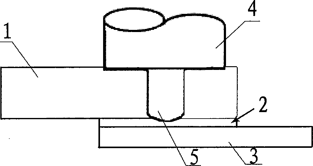
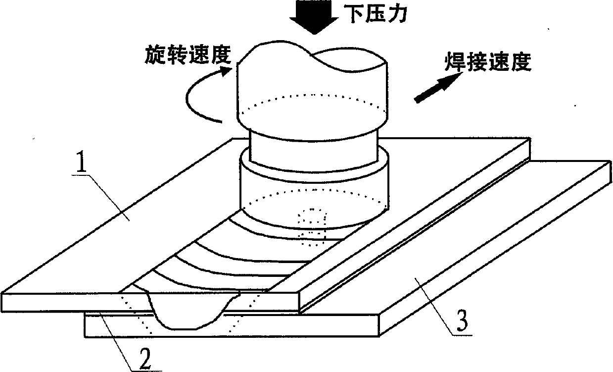
[0018] combine Figure 1 ~ Figure 3 Describe this implementation mode, this implementation mode is realized through the following steps:

[0019] Step 1. Use a steel brush to clean the contact surface and surroundings of the steel plate and aluminum plate to be welded to remove oxides on the surface of the test piece, and use organic solvent alcohol or acetone to wipe the surface of the steel plate and aluminum plate to remove oil and other sundries;

[0020] Step 2. Select a pure zinc sheet 2 with a thickness of 0.05mm according to the material to be welded, and determine the width of the sheet according to the diameter of the shaft shoulder of the stirring head. The width of the sheet is 5mm larger than the diameter of the shaft shoulder. The length of determines the length of the flake;

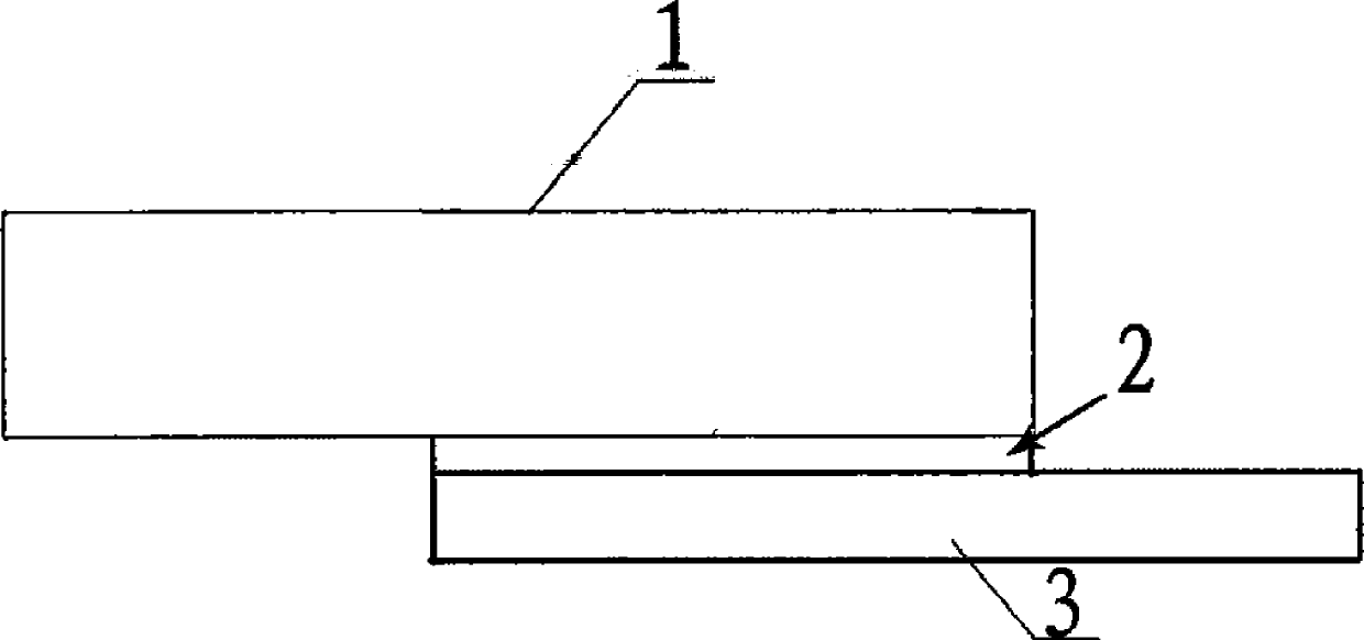
[0021] Step 3, forming a lap joint in which the aluminum plate 1 is on the top and the steel plate 2 is on the bottom, the thin sheet 2 is located in the middle of the lap joint, and is i...

Embodiment 2

[0025] Step 1. Use a steel brush to clean the contact surface and surroundings of the steel plate and aluminum plate to be welded to remove oxides on the surface of the test piece, and use organic solvent alcohol or acetone to wipe the surface of the steel plate and aluminum plate to remove oil and other sundries;

[0026] Step 2. According to the material to be welded, select an aluminum-zinc sheet with a thickness range of 0.2mm, and determine the width of the sheet according to the diameter of the shaft shoulder of the stirring head. The width of the sheet is 2mm larger than the diameter of the shaft shoulder. The length of determines the length of the flake;

[0027] Step 3, forming a lap joint with the aluminum plate at the top and the steel plate at the bottom, the thin sheet is in the middle of the lap joint and is in contact with the upper surface of the steel plate and the lower surface of the aluminum plate respectively;

[0028] Step 4. Select the range of welding p...


PUM

PropertyMeasurementUnit
Thicknessaaaaaaaaaa
Thicknessaaaaaaaaaa

Abstract

The invention discloses a brazing auxiliary friction stir welding method suitable for aluminum and steel dissimilar material lap joint. A pure zinc or aluminum and zinc sheet is added to the lap joint position of a steel plate and an aluminum plate, the sheet is molten due to heat generated by friction and deformation generated in the friction stir process, the pure zinc or aluminum and zinc sheet serves as a middle transition layer of an aluminum and steel connector, it can be avoided that brittle intermetallic compounds are formed between aluminum and steel, effective lap joint is formed between the steel plate and the aluminum plate, and eventually an aluminum and steel dissimilar material lap joint connector which is attractive in appearance of weld, excellent in mechanical property and reliable in strength can be acquired.

Description

technical field [0001] The invention relates to a friction stir welding method, in particular to a brazing-assisted friction stir welding method suitable for lap joints of aluminum and steel dissimilar materials. Background technique [0002] As an advanced solid-phase joining technology, friction stir welding has been invented by The Welding Institute (TWI) in 1991. Due to its small welding deformation, small residual stress, and good joint quality, it does not require shielding gas and Filling materials can eliminate welding defects such as pores, inclusions, cracks, etc., and do not produce arc light, smoke, noise, etc. Pollution, at the same time, it has obvious advantages such as simple welding operation, convenient automatic welding, and high welding efficiency. Friction stir welding has been used in aerospace, aviation, shipbuilding, etc. , trains, automobiles, electric power and other industrial manufacturing fields have been widely used. In recent years, environmen...

Claims


Application Information

Patent Timeline
IPC IPC(8): B23K31/02
CPCB23K1/00B23K20/122B23K28/02B23K2103/18
Inventor 黄永宪万龙郭伟强黄体方吕世雄吕宗亮王耀彬
Owner 苏州万智新能源科技有限公司
Features
  • Generate Ideas
  • Intellectual Property
  • Life Sciences
  • Materials
  • Tech Scout
  • Unparalleled Data Quality
  • Higher Quality Content
  • 60% Fewer Hallucinations
Learn More