
Device and method for improving sputtering cathode target utilization and coating uniformity

A utilization rate, cathode target technology, applied in sputtering coating, metal material coating process, coating and other directions, can solve the problem that cannot fundamentally solve the uneven axial etching of the target tube, and cannot meet the coating uniformity It can improve the utilization rate of target materials, improve the uniformity of spatial distribution, and weaken the effect of excessive etching.

Inactive Publication Date: 2016-06-01
HEFEI UNIV OF TECH
View PDF3 Cites 0 Cited by
  • Summary
  • Abstract
  • Description
  • Claims
  • Application Information

AI Technical Summary

Problems solved by technology

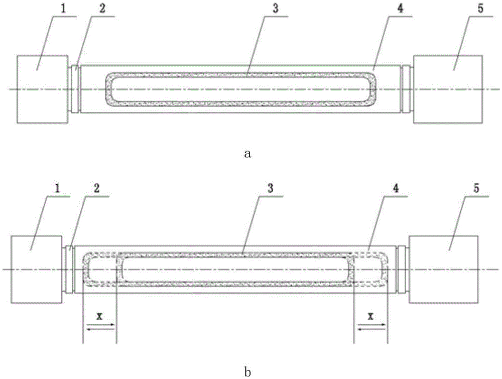
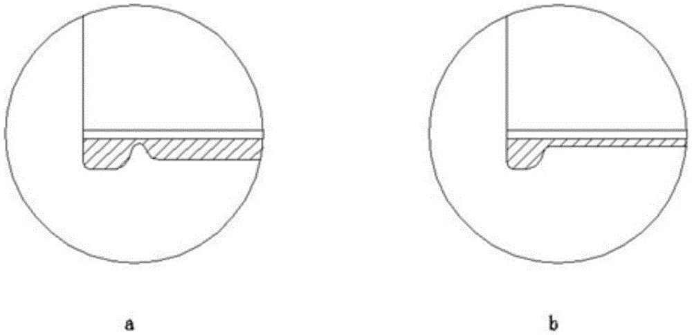
[0008] In the existing solutions, the target tube is usually processed into a "dog bone shape", or the Chinese patent CN202369634U discloses a design of adding "target caps" at both ends of the target tube. Increasing the etching time of the target at the end by thickening or shielding at both ends of the target can not fundamentally solve the fundamental situation of uneven etching of the target tube in the axial direction.
[0009] (2) The coating uniformity of the coating is not ideal at present, and there will be wavy ribbons caused by uneven coating thickness in actual production
Correspondingly, when the substrate is just below the two plasma linear distribution bands, more target particles will be deposited, which will inevitably lead to a great impact on the thickness uniformity of the deposited film, which cannot even meet the requirements of the industry. Process requirements for coating uniformity

Method used


Image

  • Device and method for improving sputtering cathode target utilization and coating uniformity
  • Device and method for improving sputtering cathode target utilization and coating uniformity
  • Device and method for improving sputtering cathode target utilization and coating uniformity

Examples


Embodiment Construction

[0032] Such as Figure 5 As shown, a device for improving sputtering cathode target utilization and coating uniformity includes a cam system movement mechanism 10, an axial reciprocating connection piece 11, a water inlet support tube 6, a magnet assembly 7, and a radial rotation movement The connector 12 and the servo motor drive mechanism 20, the axial reciprocating motion connector 11 is fixedly connected with the cam system motion mechanism 10, the radial rotation motion connector 12 is fixedly connected with the servo motor drive mechanism 20, and the water inlet The left and right ends of the support pipe 6 are respectively fixedly connected with the axial reciprocating joint 11 and the radial rotational joint 12 , and the magnet assembly 7 is fixed on the water inlet support pipe 6 .

[0033] Such as Figure 6 , 7 As shown, the cam system movement mechanism 10 includes a target end support tube 13, and a left and right support end cap 103 is arranged inside the target...


PUM


Abstract

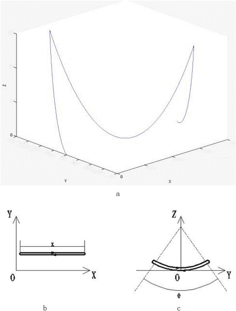
The invention discloses a device and method for improving sputtering cathode utilization rate and coating uniformity. An axial reciprocating motion connector is fixedly connected with a cam system movement mechanism; a radial rotational motion connector is fixedly connected with a servo motor drive mechanism; left and right ends of a water inlet supporting tube are fixedly connected with the axial reciprocating motion connector and the radial rotational motion connector, respectively; a magnet assembly is fixed on a water inlet supporting tube; the magnet assembly does periodic axial straight reciprocating motion and radial rotary reciprocating motion with a range permitted by three degrees of freedom of space. According to the device and method disclosed by the invention, axial etching uniformity of targets is greatly improved, so that an excessive etching phenomenon of the end parts of a target tube is weakened, formation of an etching groove in the radial direction of the end parts of the target tube is avoided, service lives of the targets are prolonged, target utilization rate is greatly increased, space distribution uniformity of sputtered target particles within a radial special angle of the target tube is improved, and therefore, quality of an obtained deposited film is greatly improved, and thickness uniformity of the coating is greatly improved.

Description

technical field [0001] The invention relates to the technical field of vacuum magnetron sputtering coating, in particular to a device and a method for improving the utilization rate of a sputtering cathode target and the uniformity of a coating. Background technique [0002] With its two advantages of high speed and low temperature, magnetron sputtering coating technology is widely used in vacuum coating industry, and has become one of the most important technologies in industrial coating production. Magnetron sputtering coating technology is mainly used in the coating production of Low-E films for building materials, ITO films for flat panel displays, and backplane films for solar cells. [0003] The main working principle of magnetron sputtering coating equipment is to use the gas glow discharge process to generate positive ions (usually argon ions when the reaction gas is argon), and these positive ions bombard the cathode with high energy under the acceleration of the el...

Claims


Application Information

Patent Timeline
Patent Type & Authority Patents(China)
IPC IPC(8): C23C14/35
Inventor 陈长琦闫清泉王国栋陈晨
Owner HEFEI UNIV OF TECH
Learn More