Floating type remote water taking device hydraulic system
What is Al technical title?
Al technical title is built by PatSnap Al team. It summarizes the technical point description of the patent document.
A remote water intake and hydraulic system technology, applied in the direction of fluid pressure actuators, servo motors, mechanical equipment, etc., can solve the problems of difficult power supply, cumbersome preparation work, poor mobility, etc., to ensure water supply efficiency and water volume, simple and novel structure , the effect of strong overall independence
Inactive Publication Date: 2014-07-23
HEFEI JULAN SAFETY TECH
View PDF7 Cites 3 Cited by
Summary
Abstract
Description
Claims
Application Information
AI Technical Summary
This helps you quickly interpret patents by identifying the three key elements:
Problems solved by technology
Method used
Benefits of technology
Problems solved by technology
Neither the water source capacity for industrial and building fire extinguishing nor the water supply capacity of the firefighting vehicles owned by the fire brigade can meet the large-scale fire extinguishing water demand, and sufficient natural water sources are usually far away from the fire scene. How to continuously and large-flow deliver the fire extinguishing water to the fire The scene is a severe challenge for the fire brigade; at the same time, as the scale of Chinese cities continues to increase, the frequency of urban waterlogging and other disasters is also increasing year by year
Therefore, how to achieve large flow, long-term and long-distance water supply and drainage is a practical problem that must be solved for current fire protection and emergency rescue; at present, the suction height of domestic fire pump units is generally about 4m-6m, and the self-priming capacity Poor, the whole unit needs to be as close as possible to the water source; the traditional domestic water supply and drainage systems are generally driven by motors, which are large in size, inconvenient to move, and poor in mobility. They must be equipped with a generator of corresponding power or a place with power supply when working; During water supply and emergency drainage, due to the limitation of the geographical environment and the influence of the weather, the power supply has become a big problem; its work is to absorb water from the open water source through internal negative pressure. When the water source reaches a certain height from the ground, it cannot be placed in the water source. The water in the pump is sucked into the pump, causing the pump to suck up, the water at the water source cannot be sucked up, the seal of the impeller generates high temperature, the seal burns, and a large amount of water leaks
And all are limited by its low flow rate, low head, low suction; the preparation work before the operation is relatively cumbersome, resulting in a long time, greatly delaying the fighter; the existing technology can not meet people's needs; in order to make up for the existing technology Insufficient, the present invention aims to provide a kind of hydraulic system of floating type remote water intake device
Method used
Image
Click on the blue label to locate the original text in one second.
Reading with bidirectional positioning of images and text.
Examples
Embodiment Construction
[0013] The technical solutions in the embodiments of the present invention will be clearly and completely described below in conjunction with the accompanying drawings in the embodiments of the present invention. Obviously, the described embodiments are only a part of the embodiments of the present invention, rather than all the embodiments. Based on the embodiments of the present invention, all other embodiments obtained by those of ordinary skill in the art without creative work shall fall within the protection scope of the present invention.
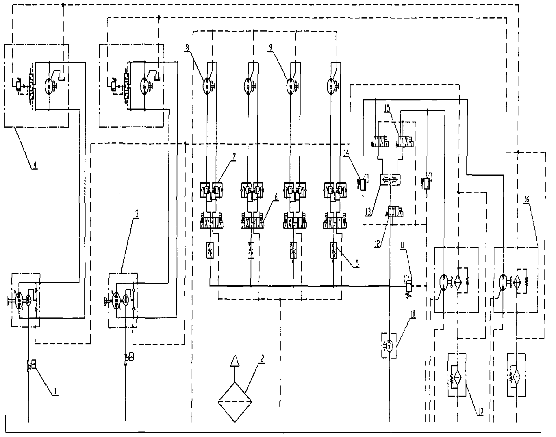
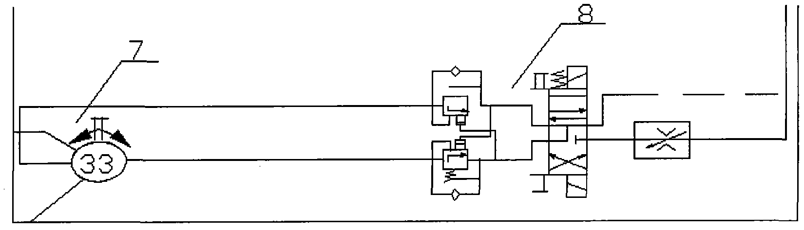
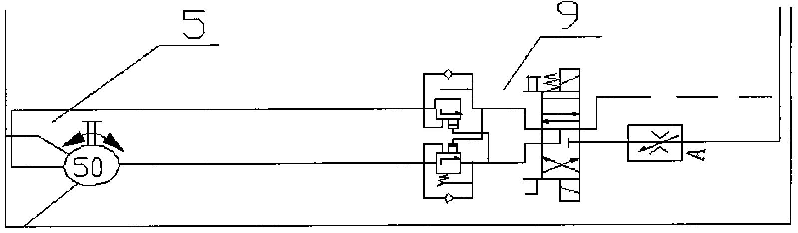
[0014] See Figure 1~6 In the embodiment of the present invention, a hydraulic system of a floating remote water intake device includes a hydraulic butterfly valve 1, an air filter 2, a variable plunger pump 3, a submersible pump drive motor 4, a speed control valve 5, and an electromagnetic reversing valve 1. 6. Two-way balancing valve 7, submersible pump recovery motor 8, tubing recovery motor 9, gear pump 10, overflow valve 11, electr...
PUM
Abstract
The invention discloses a floating type remote water taking device hydraulic system which comprises a hydraulic butterfly valve, an air filter, a variable displacement piston pump, a submerged pump driving motor, a speed control valve, a first solenoid directional valve, a bidirectional balance valve, a submerged pump recycling motor, an oil pipe recycling motor, a gear pump, an overflow valve, a second solenoid directional valve, a flow divider valve, a second overflow valve, a third solenoid directional valve, a hydraulic oil cooler and an oil return filter. According to the floating type remote water taking device hydraulic system, variable frequency constant pressure water supply is adopted by the whole system, pressure set on site is used as a parameter, the output frequency of a frequency converter is controlled through a microcomputer to regulate the rotating speeds of the motors automatically, the closed-loop regulation of water pressure of a pipe network is achieved, the system can be stabilized at a set pressure value constantly and automatically, water supply efficiency is guaranteed, and requirements of water yield are met. The overall floating type remote water taking device hydraulic system is strong in independence, large in flow, high in lift, simple and novel in structure, and convenient and fast to use.
Description
Technical field [0001] The invention relates to the technical field of remote water intake applications, in particular to a hydraulic system of a floating remote water intake device. Background technique [0002] With the rapid development of the current social economy, the fire situation has become more complicated. Whether it is the water supply capacity for industrial and building fire extinguishing, or the water supply capacity of fire fighting vehicles owned by the firefighting force, they cannot meet the demand for large-scale firefighting water, and sufficient natural water sources are usually far away from the fire site. How to continuously and large flow of firefighting water to the fire The scene is a severe challenge for the firefighting forces; at the same time, as the scale of Chinese cities continues to increase, the frequency of disasters such as urban waterlogging has also increased year by year. Therefore, how to achieve large flow, continuous long-term and long...
Claims
Application Information
Patent Timeline
Application Date:The date an application was filed.
Publication Date:The date a patent or application was officially published.
First Publication Date:The earliest publication date of a patent with the same application number.
Issue Date:Publication date of the patent grant document.
PCT Entry Date:The Entry date of PCT National Phase.
Estimated Expiry Date:The statutory expiry date of a patent right according to the Patent Law, and it is the longest term of protection that the patent right can achieve without the termination of the patent right due to other reasons(Term extension factor has been taken into account ).
Invalid Date:Actual expiry date is based on effective date or publication date of legal transaction data of invalid patent.