Method and device for defrosting through combination operation of multiple air heat source heat exchangers

An air heat exchanger and heat exchanger technology, applied in refrigeration and liquefaction, lighting and heating equipment, damage protection, etc., can solve the problems of fins affecting heat exchange effect, air side fin corrosion, affecting the surrounding environment, etc. Achieve the effect of simple installation, high energy efficiency ratio and low investment cost

Active Publication Date: 2014-07-23
JIANGSU TONGSHENG HEAT EXCHANGER
View PDF6 Cites 13 Cited by
  • Summary
  • Abstract
  • Description
  • Claims
  • Application Information

AI Technical Summary

Problems solved by technology

[0016] The disadvantage of the above technology is that the process is complicated, and it is necessary to add a thickening device, or other defrosting auxiliary spraying devices, etc., which is not only costly, but also the drift of chlorides will affect the surrounding environment and have a certain corrosion effect on the air side fins. Or contaminating the fins affects its heat transfer effect
We also know that water vapor in the air contains huge latent heat, which can even account for more than 30% of the heat of the entire air energy. How to use the latent heat of water vapor in the air to turn it into a benefit is of great significance, unlike the current Part of the latent heat of water vapor is lost due to defrosting technology such as antifreeze spray, electric heating, hot air blowing, reheating, etc., and the cost of increasing operating costs or increasing investment costs

Method used


Image

  • Method and device for defrosting through combination operation of multiple air heat source heat exchangers

Examples


Embodiment Construction

[0056] The present invention will be described in further detail below in conjunction with the accompanying drawings and embodiments.

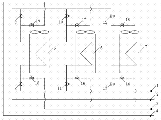
[0057] With reference to the accompanying drawings, the multi-air heat source heat exchanger combined defrosting device of the present embodiment includes No. 1 air heat exchanger 5, No. 2 air heat exchanger 6, and No. 3 air heat exchanger 7. The No. 1 air heat exchanger The inlet of the heat exchanger 5 is provided with two branch pipes, one branch pipe is equipped with an electronic valve I9, and is connected to the evaporator outlet of the main unit of the workstation through the pipe I1, and the other branch pipe is equipped with an electronic valve II18, and through the pipe Road III3 is connected to the condenser outlet of the workstation host, and the outlet of the No. 1 air heat exchanger 5 is provided with two branch pipes, one of which is equipped with an electronic valve III8, and is connected to the evaporator of the workstation hos...


PUM


Abstract

The invention provides a method and device for defrosting through combination operation of multiple air heat source heat exchangers. According to the method, the mode that defrosting is conducted on a heat exchange unit in turn is adopted, thermal fluids of a condenser of a main machine of a workstation are led into a unit body to be defrosted to conduct heat exchange with frost on a fin outside the heat exchanger of the unit body so as to remove the frost and melt the ice, the main machine does not need to be in a standby state, and the heating work of the main machine in the workstation can continue in the defrosting process. The defrosting process includes the specific steps that an electronic valve, connected with an evaporator in series, of an air heat exchanger to be defrosted is shut down, an electronic valve connected with the condenser in series is opened, and the thermal fluids from the condenser flow into the air heat exchanger to be defrosted to conduct defrosting. The invention further provides the device for defrosting through combination operation of the multiple air heat source heat exchangers. The method and device for defrosting through combination operation of the multiple air heat source heat exchangers are wide in applicable range, capable of achieving the purpose of controlling defrosting through maximum average heating load, and capable of saving energy sources and water sources and having great significance in easing environment pressure and eliminating hazes; a traditional heating mode by using a boiler can be abandoned truly.

Description

technical field [0001] The invention relates to a method and a device for defrosting multiple air heat source heat exchangers. Background technique [0002] With the continuous growth of the population and the rapid development of the economy, the consumption and depletion of mineral energy have been exacerbated, and at the same time, serious pollution and damage have been brought to the environment. In recent years, environmental pollution has been particularly serious. Many large and medium-sized cities have frequent occurrences of smog due to heating in winter, which not only harms the health of urban residents, but also affects crop production and reduces production. For this reason, people are finding the outlet of energy with great effort: the one, save energy, the 2nd, develop new energy. So far, on the one hand, energy-saving technology is based on the first law of thermodynamics, starting from the quantitative aspect, reducing various losses and waste; on the other...

Claims


Application Information

Patent Timeline
Patent Type & Authority Applications(China)
IPC IPC(8): F25B47/00F25B41/04F25B41/20
Inventor 陈友明刘小江徐雨淋刘赟肖文瑜
Owner JIANGSU TONGSHENG HEAT EXCHANGER
Why Eureka
Try Eureka