Cooling device

A cooling device and cooling water technology, applied in cooling/ventilation devices, electromechanical devices, electrical devices, etc., can solve problems such as thermal damage, and achieve efficient cooling and good responsiveness

Active Publication Date: 2014-07-23
HITACHI ASTEMO LTD
View PDF7 Cites 20 Cited by
  • Summary
  • Abstract
  • Description
  • Claims
  • Application Information

AI Technical Summary

Problems solved by technology

[0003] However, it is known that power converters used in electric vehicles such as electric vehicles and hybrid vehicles as described above may be thermally destroyed due to heat generated by the switching operation of the switching elements inside.

Method used


Image

  • Cooling device
  • Cooling device
  • Cooling device

Examples


Embodiment 1

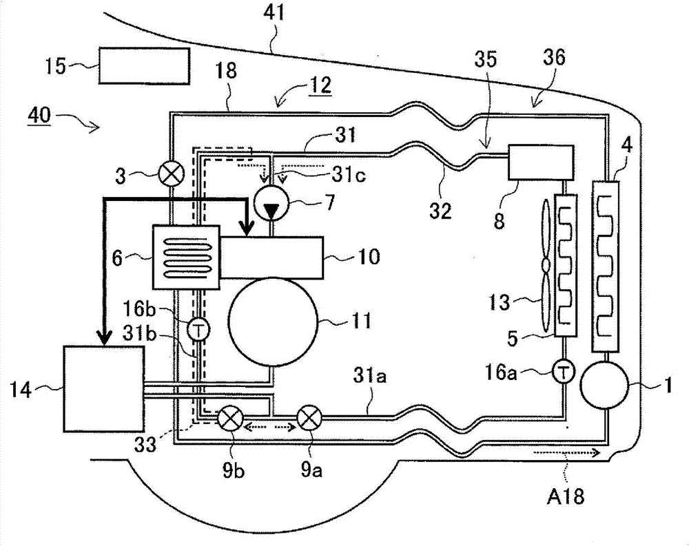
[0030] figure 1 The basic structure of the front interior of the vehicle according to the first embodiment of the cooling device according to the present invention is shown. Here, the figure shows an example in which the cooling device 12 of the first embodiment is applied to a front-wheel drive electric vehicle. The right side of the figure is the direction of travel of the vehicle 41. The system 40 is mounted near the front wheels of a vehicle 41 . It should be noted that the cooling device 12 of the first embodiment can also be applied to a rear-wheel drive or four-wheel drive electric vehicle, or a hybrid electric vehicle equipped with an engine, or the like.

[0031] The electric drive system 40 of the illustrated electric vehicle 41 includes a battery 14 that stores drive energy, a power converter 10 that controls the drive power supplied to the motor 11 using the power supplied from the battery 14 , and drives An electric motor 11 that generates torque (driving force)...

Embodiment 2

[0076] Figure 4 The basic structure of the front interior of the vehicle according to the second embodiment of the cooling device of the present invention is shown. In this embodiment 2, the second flow path 31b of the water cooling system 35 of the above-mentioned embodiment 1 is also used as a flow path for heating the vehicle interior. The same symbols are assigned and detailed descriptions thereof are omitted.

[0077] The cooling device 12A of the second embodiment shown in the figure is compared to the cooling device 12 of the first embodiment described above, and a heater (heat exchanger) 25 for heating the vehicle interior is attached to the second flow path 31bA of the water cooling system 35A. and heating element 26. The heater 25 is a device for heating air introduced into the vehicle interior with hot water. In addition, the heating element 26 is a device that converts electric power into thermal energy, such as a resistance heating element. It should be noted...


PUM


Abstract

In order to provide an electric-vehicle cooling device using both a refrigeration cycle system and a water cooling system in combination, that can cool such devices as an electric motor, power converter, or storage cell with favorable responsiveness, a cooling device (12) is provided with a water cooling system (35) for cooling a body to be cooled by circulating cooling water, and a refrigeration cycle system (36) for using a gas-liquid phase change of a refrigerant to cool the cooling water to the outside air temperature or lower. The water cooling system (35) is provided with the following: a first flow path (31a) for causing to flow to the body to be cooled cooling water that has been cooled by a radiator (5) for radiating the heat of the cooling water to the outside air; a second flow path (31b) for causing cooling water that has been cooled to the outside air temperature or lower by an evaporator (6) of the refrigeration cycle system (36) to flow to the body to be cooled located in the first flow path (31a); and flow rate control means (9a, 9b) for controlling the flow rates of the cooling water flowing through the first flow path (31a) and the second flow path (31b).

Description

technical field [0001] The present invention relates to a cooling device, for example, to a cooling device for an electric vehicle using a water cooling system and a refrigeration cycle system in combination. Background technique [0002] In electric vehicles such as electric vehicles and hybrid vehicles, a power converter (inverter) converts DC power supplied from a high-voltage storage battery (such as a lithium-ion battery) into AC power, and uses this AC power to drive a motor (such as a three AC motor) rotates, thereby generating the driving force of the vehicle. In addition, when the vehicle is decelerating, regenerative energy obtained by regenerative power generation of the electric motor is stored in the battery, thereby reducing waste of energy and realizing efficient energy utilization. [0003] However, it is known that power converters used in electric vehicles such as electric vehicles and hybrid vehicles as described above may be thermally destroyed due to he...

Claims


Application Information

Patent Timeline
Patent Type & Authority Applications(China)
IPC IPC(8): B60H1/00B60H1/08H02K9/19
CPCH02K9/19B60H1/00392B60H1/08H02M7/003H02K2213/09B60L1/003B60L1/04B60L3/003B60L3/0061B60L15/20B60L2240/12B60L2240/34B60L2240/36B60L2240/421B60L2240/423B60L2240/425B60L2240/525B60L2240/545B60L2240/662B60L2270/145Y02T90/16Y02T10/72B60L50/51B60L58/26Y02T10/64Y02T10/70B60H1/00007
Inventor 横山笃尾坂忠史秋山悠基宫崎英树
Owner HITACHI ASTEMO LTD
Why Eureka
Try Eureka