Liquid crystal display device, polarizing plate and polarizer protective film
A technology of liquid crystal display devices and polarizers, which is applied in polarizing elements, optics, optical elements, etc., can solve the problems of expensive TAC film, inability to obtain sufficient mechanical strength, and easy deterioration of polarizers, and achieve good visibility.
- Summary
- Abstract
- Description
- Claims
- Application Information
AI Technical Summary
Problems solved by technology
Method used
Image
Examples
Embodiment
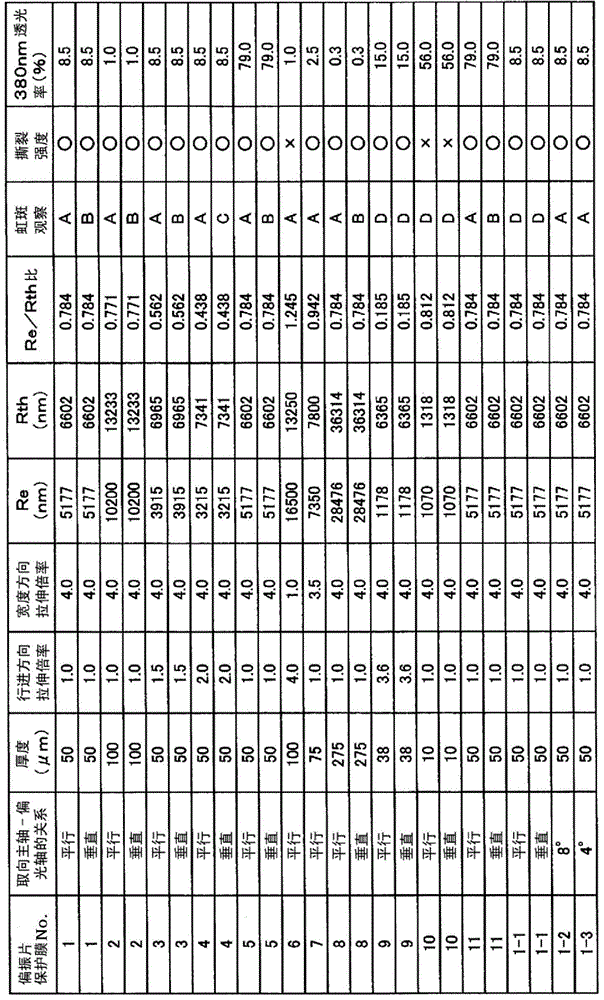
[0078] The present invention will be described in more detail below with reference to the examples, but the present invention is not limited by the following examples, and can also be implemented with appropriate changes within the scope of the gist of the present invention, and these implementation modes are also included in this document. within the scope of protection of the invention. In addition, the evaluation methods of the physical properties in the following examples are as follows.
[0079] (1) Film orientation principal axis
[0080] The orientation principal axis direction of the film was determined using a molecular orientation meter (Molecular Orientation Meter MOA-6004, manufactured by Oji Scientific Instruments, Ltd.).
[0081] (2) Retardation (Re)
[0082] Retardation refers to the parameter defined by the product (ΔNxy×d) of the anisotropy (ΔNxy=|Nx-Ny|) of the biaxial refractive index on the film and the film thickness d (nm), which is Displays the scale ...
manufacture example 1
[0097] (Manufacturing example 1-polyester A)
[0098] Elevate the temperature of the esterification reactor, and when it reaches 200°C, add 86.4 parts by mass of terephthalic acid and 64.6 parts by mass of ethylene glycol, and add 0.017 parts by mass of antimony trioxide and 0.064 parts by mass of magnesium acetate as catalysts while stirring. Hydrate, 0.16 parts by mass of triethylamine. Next, pressurization and temperature raising were performed, and after pressurized esterification reaction was performed on the conditions of gauge pressure 0.34MPa and 240 degreeC, the esterification reactor was returned to normal pressure, and 0.014 mass parts of phosphoric acid was added. Furthermore, it heated up to 260 degreeC over 15 minutes, and added 0.012 mass parts of trimethyl phosphates. Then, after 15 minutes, dispersion treatment was carried out with a high-pressure disperser, and after 15 minutes, the obtained esterification reaction product was transferred to a polycondensati...
manufacture example 2
[0100] (Manufacturing example 2-polyester B)
[0101] 10 parts by mass of dried UV absorber (2,2'-(1,4-phenylene)bis(4H-3,1-benzoxazin-4-one), 90 parts by mass of particle-free PET (A) (intrinsic viscosity: 0.62dl / g) is mixed, and a mixing extruder is used to obtain polyethylene terephthalate resin (B) (hereinafter abbreviated as PET (B) ).
PUM
| Property | Measurement | Unit |
|---|---|---|
| particle size | aaaaa | aaaaa |
| temperature | aaaaa | aaaaa |
| thickness | aaaaa | aaaaa |
Abstract
Description
Claims
Application Information
 - R&D
- Intellectual Property
- Life Sciences
- Materials
- Tech Scout
- Unparalleled Data Quality
- Higher Quality Content
- 60% Fewer Hallucinations
Browse by: Latest US Patents, China's latest patents, Technical Efficacy Thesaurus, Application Domain, Technology Topic, Popular Technical Reports.
© 2025 PatSnap. All rights reserved.Legal|Privacy policy|Modern Slavery Act Transparency Statement|Sitemap|About US| Contact US: help@patsnap.com

