Jet liquid immersion ultrasonic detection method and liquid sprayer

A technology of ultrasonic detection and detection method, which is applied in the direction of spraying device, spraying device, measuring/indicating equipment, etc., which can solve the problems of poor measurement stability, restrained sound wave energy propagation, complex structure, etc., and achieve high liquid column stiffness and strong convergence ability , the effect of simple operation

Active Publication Date: 2015-12-30
DALIAN UNIV OF TECH
View PDF5 Cites 2 Cited by
  • Summary
  • Abstract
  • Description
  • Claims
  • Application Information

AI Technical Summary

Problems solved by technology

In 2010, Han Zandong et al. invented a nozzle for ultrasonic non-destructive testing with a relatively simple structure in the invention patent CN101672828A. Large, high turbulence intensity, resulting in significant turbulence-induced measurement noise
In 2012, in the invention patent CN102680585A, based on the Solidworks software platform, Xu Zhinong et al. proposed a rapid design method for a layered and combined water spray coupling device to meet the size requirements of ultrasonic probes of different specifications. The structure has certain flexibility, but in the design Only geometric conditions such as probe size and ultrasonic focal length are considered, and the constraints of the flow field state are not mentioned.
In order to avoid the impact of clutter caused by multiple reflections of ultrasonic waves in the sprinkler, on the one hand, a porous screen structure with wave-absorbing materials is selected; The turbulent flow at the nozzle is very strong, which seriously restricts the propagation of sound wave energy, and the measurement stability is poor

Method used


Image

  • Jet liquid immersion ultrasonic detection method and liquid sprayer
  • Jet liquid immersion ultrasonic detection method and liquid sprayer
  • Jet liquid immersion ultrasonic detection method and liquid sprayer

Examples


Embodiment Construction

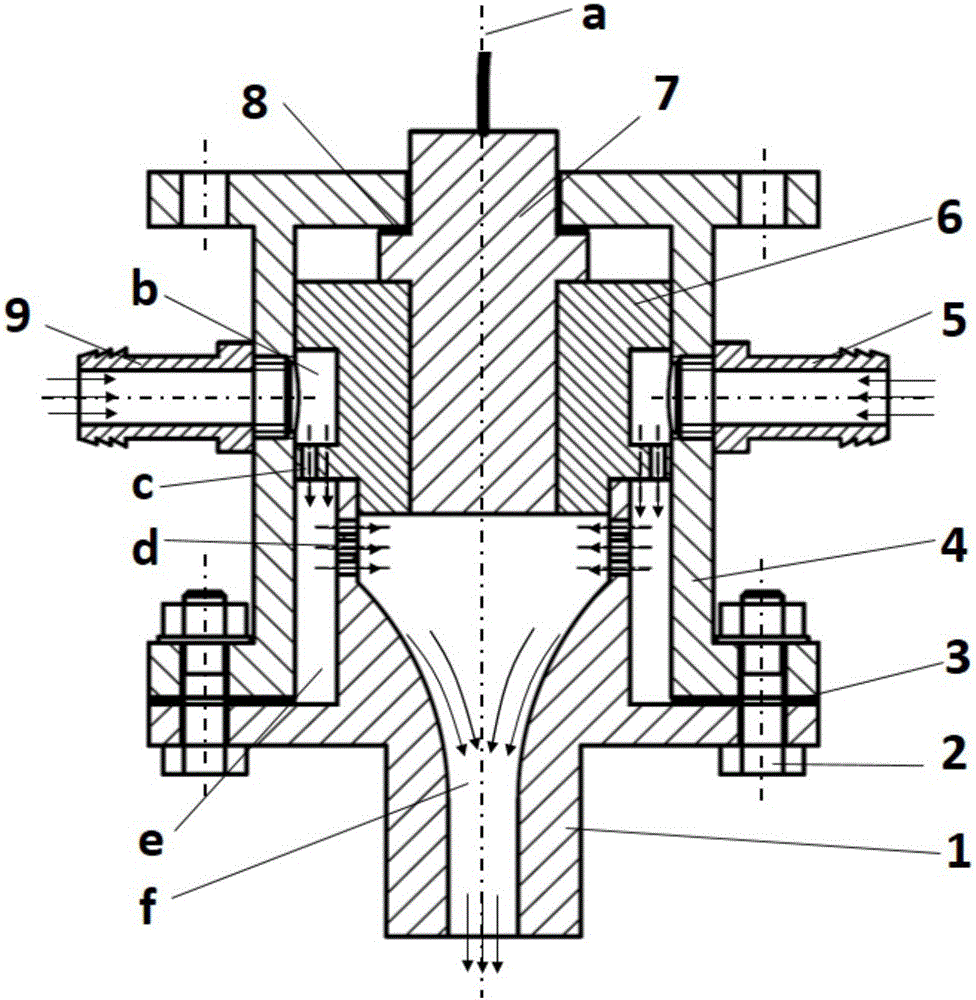
[0013] The specific embodiments of the present invention will be described in detail below with reference to the accompanying drawings: first, the liquid sprayer 14 is connected to the spindle adapter mechanism 11 through four second bolt assemblies 13 evenly distributed in the circumferential direction, and then the spindle adapter mechanism 11 is installed on the machine tool spindle 10 , the numerical control machine tool automatically controls the liquid ejector 14 and the ultrasonic probe 7 to move according to the pre-designed measurement path, and measures the measured part 15, as shown in the appendix Figure 4 shown.

[0014] In order to realize the reliable detection of jet liquid immersion ultrasonic, the liquid jet 14 must meet the mixed constraints of the focused sound field geometry of the ultrasonic probe 6 and the state of the couplant flow field. Stable laminar flow field and rigid liquid column.

[0015] Liquid sprayer structure assembly: first, the second s...


PUM


Abstract

The invention belongs to the technical field of ultrasonic non-destructive detection and relates to a jet flow immersion ultrasonic detecting method and a liquid sprayer. According to the detection method, a symmetrical radial flow injection mode is adopted for controlling coupling agents in a flowing mode, so that uniformity of injected flow and initial speed are ensured. A double-layer multi-hole screen structure is arranged on a coupling agent flowing channel, so that double-layer rectification is achieved to obtain a stable laminar condition. The liquid sprayer is composed of a nozzle, a first bolt assembly, a first sealing ring, a liquid sprayer base body, a first liquid injection nozzle, a probe clamping sleeve, a second sealing ring and a second liquid injection nozzle. Due to the reverse arc inner surface of the nozzle, the possibility that due to the fact that high-pressure flowing liquid impacts the inner wall, turbulence is formed on the inner wall is reduced, and the turbulence intensity level on an ultrasonic transmitting channel is lowered; the number of assemblies in the liquid sprayer is small, and therefore the structure is compact and simple; the method is used for carry out ultrasonic detection on focus type ultrasonic probe jet flow immersion, parts can be detected automatically on machines, operation is easy to carry out, the structure is reliable, and the efficiency is high.

Description

technical field [0001] The invention belongs to the technical field of ultrasonic non-destructive testing, and particularly relates to a jet liquid immersion ultrasonic testing method and a liquid sprayer. Background technique [0002] Jet immersion ultrasonic testing is one of the important methods of ultrasonic testing. During the inspection process, the ultrasonic probe immersed in the coupled flow field inspects the workpiece by transmitting focused ultrasonic beams and receiving reflected echoes. The method has the advantages of non-contact, strong sonic penetration, non-destructive, high sensitivity, high degree of automation, simple operation, and light equipment. [0003] The liquid jet is an important part of the jet liquid immersion ultrasonic testing system. It rectifies the pumped couplant to form a stable high-pressure jet liquid column. The transmission provides a safe channel; on the other hand, the transmittance of the sound intensity at the liquid / solid in...

Claims


Application Information

Patent Timeline
Patent Type & Authority Patents(China)
IPC IPC(8): B23Q17/20B05B1/34
CPCB05B1/34B23Q17/20
Inventor 刘海波王永青王振华贾振元盛贤君廉盟薄其乐王福吉杨睿康仁科
Owner DALIAN UNIV OF TECH
Why Eureka
Try Eureka