
Pipeline strain real-time detector suitable for high-temperature environment

A real-time detector and pipeline strain technology, applied in instruments, measuring devices, optical devices, etc., can solve the problems of low precision, large workload, long test period, etc., and achieve fast dynamic response, low cost, and light weight. Effect

Inactive Publication Date: 2014-08-06
QINGDAO ACAD FOR OPTO ELECTRONICS ENG
View PDF7 Cites 16 Cited by
  • Summary
  • Abstract
  • Description
  • Claims
  • Application Information

AI Technical Summary

Problems solved by technology

However, there are disadvantages in these two methods: firstly, the above two methods need to be shut down before testing can be performed; secondly, both methods need to manually measure the performance of the pipeline for a long time and record the data, which not only requires a large workload and high cost , the accuracy is not high, and the test period is long; the most important thing is that neither method can test the pipeline in operation
[0006] To sum up, none of the currently used real-time detection methods can satisfy the real-time detection of high-temperature pipelines, and the real-time detection of high-temperature pipeline strain urgently requires the development of more suitable technical devices.

Method used


Image

  • Pipeline strain real-time detector suitable for high-temperature environment
  • Pipeline strain real-time detector suitable for high-temperature environment
  • Pipeline strain real-time detector suitable for high-temperature environment

Examples


Embodiment 1

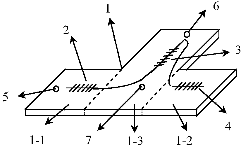
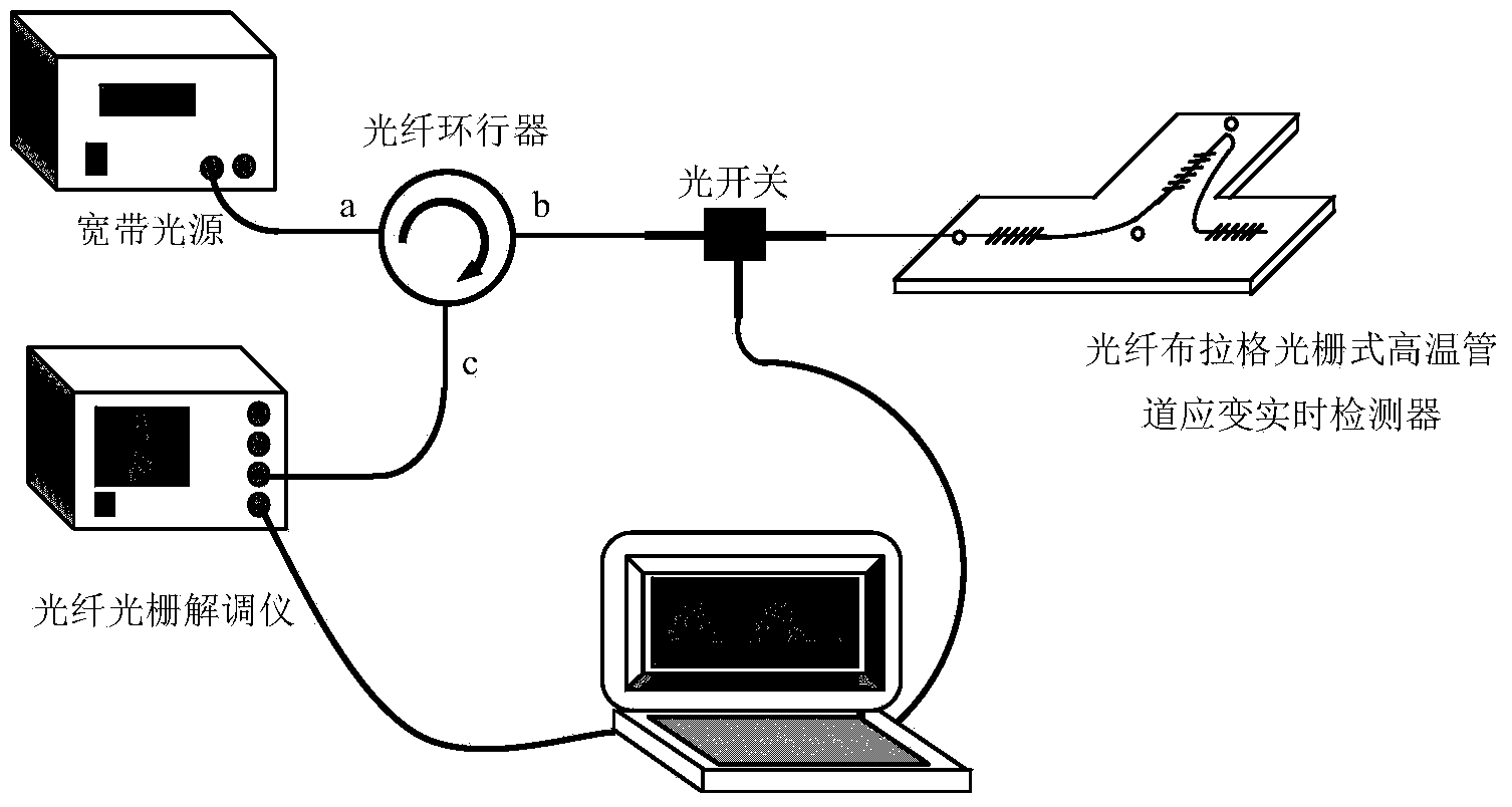
[0047] figure 1 It is a kind of fiber grating type pipe strain real-time detector suitable for high temperature environment used in embodiment 1, embodiment 2 and embodiment 3 of the present invention, which includes sensitive diaphragm 1, axial strain sensitive diaphragm 1- 1. Temperature-sensitive diaphragm 1-2, transverse strain-sensitive diaphragm 1-3, high-temperature optical fiber grating axial strain sensor 2, high-temperature optical fiber grating lateral strain sensor 3, high-temperature optical fiber grating temperature sensor 4, the first welding point 5, the second Second welding point 6, third welding point 7. The sensitive diaphragm 1 is fixed on the high-temperature pipeline to be tested through the first welding point 5, the second welding point 6, and the third welding point 7, and the line formed by the first welding point 5 and the third welding point 7 is in line with the axis of the high-temperature pipeline parallel. Wherein the two ends of the high tem...

Embodiment 2

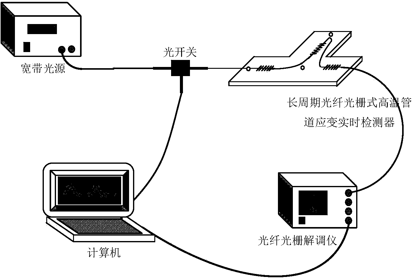
[0062] The difference from Example 1 is that the high temperature fiber grating axial strain sensor 2, the high temperature fiber grating transverse strain sensor 3 and the high temperature fiber grating temperature sensor 4 are high temperature long period fiber grating sensors with the same material, structure and size, but The three characteristic center wavelengths are different.

[0063] The three are all made of Polyimide high temperature resistant fiber grating, the length is 8cm, the grating diameter is 125um, the bandwidth is about 4nm, the wave trough spectral width is 35nm, and the maximum attenuation is 18dB, but the characteristic central wavelength of the three is different, respectively lambda 2 =1533nm,λ 3 =1560nm,λ 4 = 1590nm. The long-period fiber grating sensor is a transmission wavelength coding sensor device, which has a corresponding characteristic wavelength shift for temperature and strain. Using a fiber grating demodulator to detect the transmitted ...

Embodiment 3

[0075] Such as Figure 4 As shown, the difference from Example 1 is that on the basis of Example 1, n (n≥2) sensitive diaphragms are arranged in parallel on the high-temperature pipeline, the purpose of which is to distribute the high-temperature pipeline in multiple points type network detection.

[0076] When the outgoing light wave of the broadband light source passes through the optical fiber circulator, under the control of the optical switch, it enters the serially connected end of the n groups of fiber Bragg grating type pipeline strain real-time detectors.

[0077] Apply strain Δε to the n fiber Bragg grating real-time pipeline strain detectors mentioned above, and the light reflected by the fiber Bragg grating enters the fiber grating demodulator through the fiber circulator, and the computer connected to the demodulator is used to monitor each group of sensors. Center wavelength shift of high temperature fiber Bragg grating.

[0078] For each high-temperature pipel...


PUM

PropertyMeasurementUnit
Horizontal lengthaaaaaaaaaa
Longitudinal lengthaaaaaaaaaa
Horizontal lengthaaaaaaaaaa

Abstract

The invention provides a fiber bragg grating type pipeline strain real-time detector. The fiber bragg grating type pipeline strain real-time detector comprises a sensitive membrane plate and high-temperature fiber bragg grating sensors, wherein the high-temperature fiber bragg grating sensors comprise the high-temperature fiber bragg grating axial strain sensor, the high-temperature fiber bragg grating transverse strain sensor and the high-temperature fiber bragg grating temperature sensor. The minimum straight-line distance between the high-temperature fiber bragg grating transverse strain sensor and a line formed by the high-temperature fiber bragg grating axial strain sensor and the high-temperature fiber bragg grating temperature sensor is not less than 10 cm. The strain real-time detector can detect two-dimensional strain situations of a pipeline under a high-temperature environment, and temperature compensation is achieved in a sensing system. The fiber bragg grating type pipeline strain real-time detector has the advantages of being resistant to electromagnetic interference, high in precision, rapid in dynamic response, small in size, low in weight and the like, and further has reliability, stability and simplicity. Meanwhile, a plurality of strain real-time detectors are arranged and used so that multipoint distributed networking detection can be conducted on the high-temperature pipeline.

Description

technical field [0001] The invention belongs to the technical field of optical fiber sensing equipment components, and in particular relates to an optical fiber grating type real-time strain detector for pipelines suitable for high-temperature environments. Background technique [0002] With the continuous expansion of energy mining scale, high-temperature pipelines have been widely used in petrochemical, aerospace, steel energy, environmental protection, pharmaceuticals and other industries that are closely related to the lifeline of the national economy. Every year there are high-temperature pipeline explosions and leakage accidents, and the prevention of pipe explosions has become the focus of attention. A large number of accident statistics show that the main causes of leakage and explosion of high-temperature pipelines are pipe wall corrosion thinning and high-temperature creep. Moreover, the failure strain of the outer wall of the high-temperature pipeline is a nonlin...

Claims


Application Information

Patent Timeline
IPC IPC(8): G01B11/16
Inventor 张铭田维坚
Owner QINGDAO ACAD FOR OPTO ELECTRONICS ENG
Learn More