Novel ejector used for supercritical fluid jet dying

A supercritical fluid and ejector technology, which is applied in solvent dyeing, equipment configuration for processing textile materials, etc., can solve the problems of dyeing dead zone of the dyed object, affecting the dyeing quality, etc., and achieves elimination of deformation and tension damage, excellent craftsmanship, and difficulty in The effect of dyed dead zones

Inactive Publication Date: 2014-08-13
SHANDONG UNIV
View PDF6 Cites 8 Cited by
  • Summary
  • Abstract
  • Description
  • Claims
  • Application Information

AI Technical Summary

Problems solved by technology

This patent overcomes the shortcoming that the dyed object is easily damaged by the high-pressure jet by using a hollow dyeing roller made of porous material, but...

Method used


Image

  • Novel ejector used for supercritical fluid jet dying
  • Novel ejector used for supercritical fluid jet dying
  • Novel ejector used for supercritical fluid jet dying

Examples


Embodiment 1

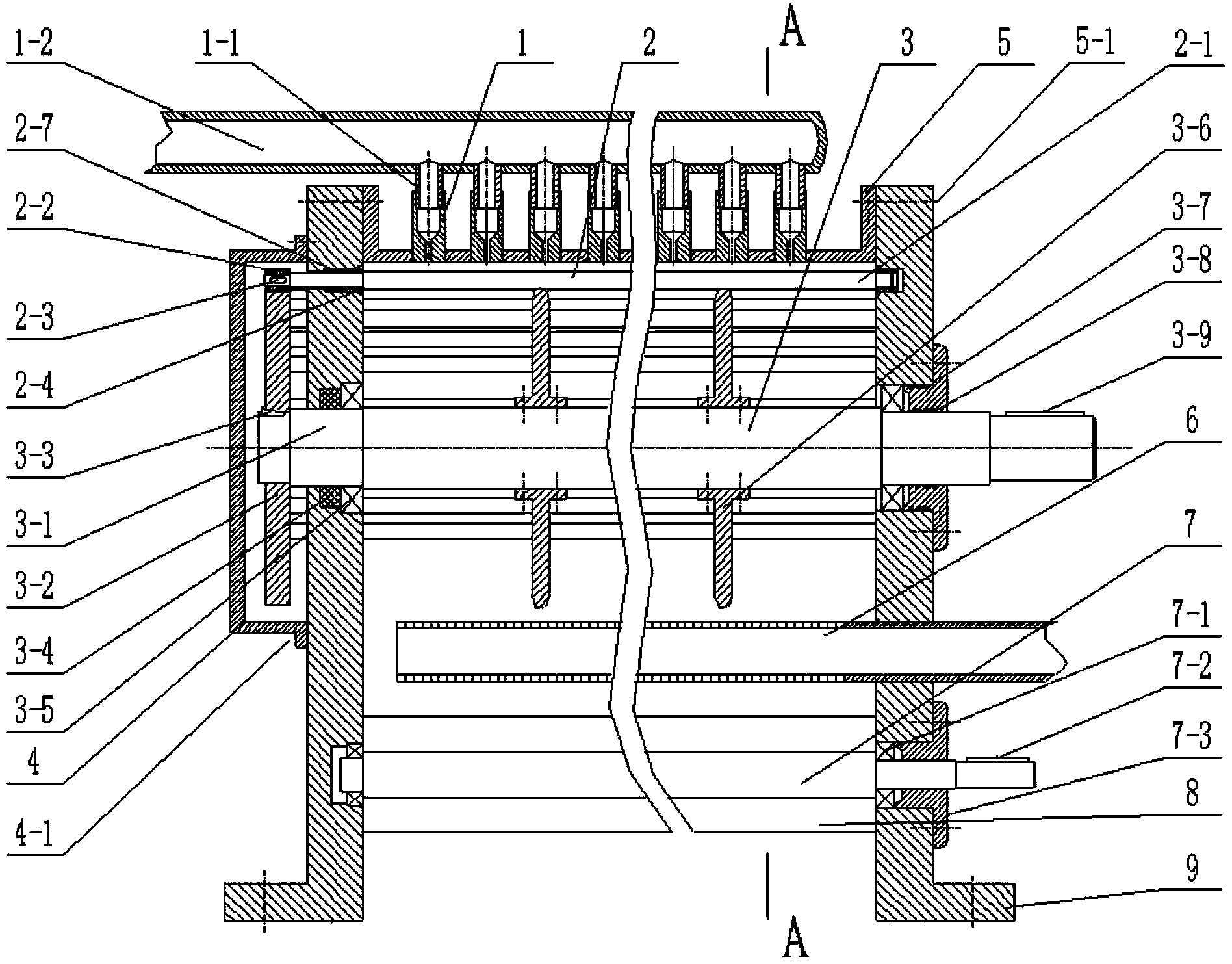
[0021] Embodiment one, the supercritical fluid jet dyeing injector when the gear drives the rolling washing roller, such as figure 1 , image 3 , Figure 4 , Figure 5 and Figure 6 shown.

[0022] The injector described in this embodiment is composed of nozzle 1, nozzle branch pipe 1-1, nozzle main pipe 1-2, squirrel cage type washing and dyeing cylinder 2, transmission support rotor 3, sealing cover 4, fairing cover 5, return pipe 6, overflow resistance Roller 7, cloth guide roller 8, side wall plate 9, baffle plate 10 constitute.

[0023]Nozzle 1, nozzle branch pipe 1-1 and nozzle main pipe 1-2 are made of stainless steel. Nozzle 1 is a through-hole structure with the same hole diameter as that of nozzle branch pipe 1-1 and a hole diameter of 0.1-1 mm at one end. Nozzle 1 and nozzle branch pipe 1- 1 is fixedly connected by welding or threaded connection, the nozzle branch pipe 1-1 and the nozzle main pipe 1-2 are connected by welding; for the dyed object 11 with a widt...

Embodiment 2

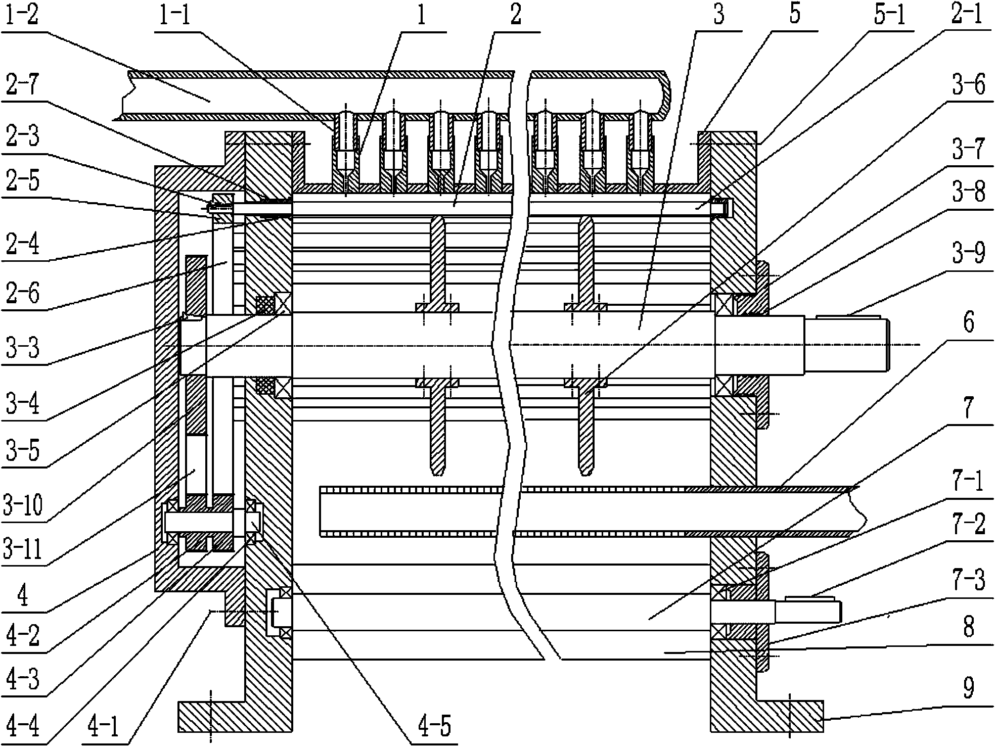
[0025] Embodiment two, when synchronous belt drives the injector of supercritical fluid spraying and dyeing when rolling dyeing roller, as figure 2 , image 3 , Figure 5 and Figure 6 shown.

[0026] The injector described in this embodiment is composed of nozzle 1, nozzle branch pipe 1-1, nozzle main pipe 1-2, squirrel cage type washing and dyeing cylinder 2, transmission support rotor 3, sealing cover 4, fairing cover 5, return pipe 6, overflow resistance Roller 7, cloth guide roller 8, side wall plate 9, baffle plate 10 constitute.

[0027] Nozzle 1, nozzle branch pipe 1-1 and nozzle main pipe 1-2 are made of stainless steel. Nozzle 1 is a through-hole structure with the same hole diameter as that of nozzle branch pipe 1-1 and a hole diameter of 0.1-1 mm at one end. Nozzle 1 and nozzle branch pipe 1- 1 The connection is fixed by welding or threaded connection, the nozzle branch pipe 1-1 and the nozzle main pipe 1-2 are connected by welding; for the dyed object 11 with...

Embodiment 3

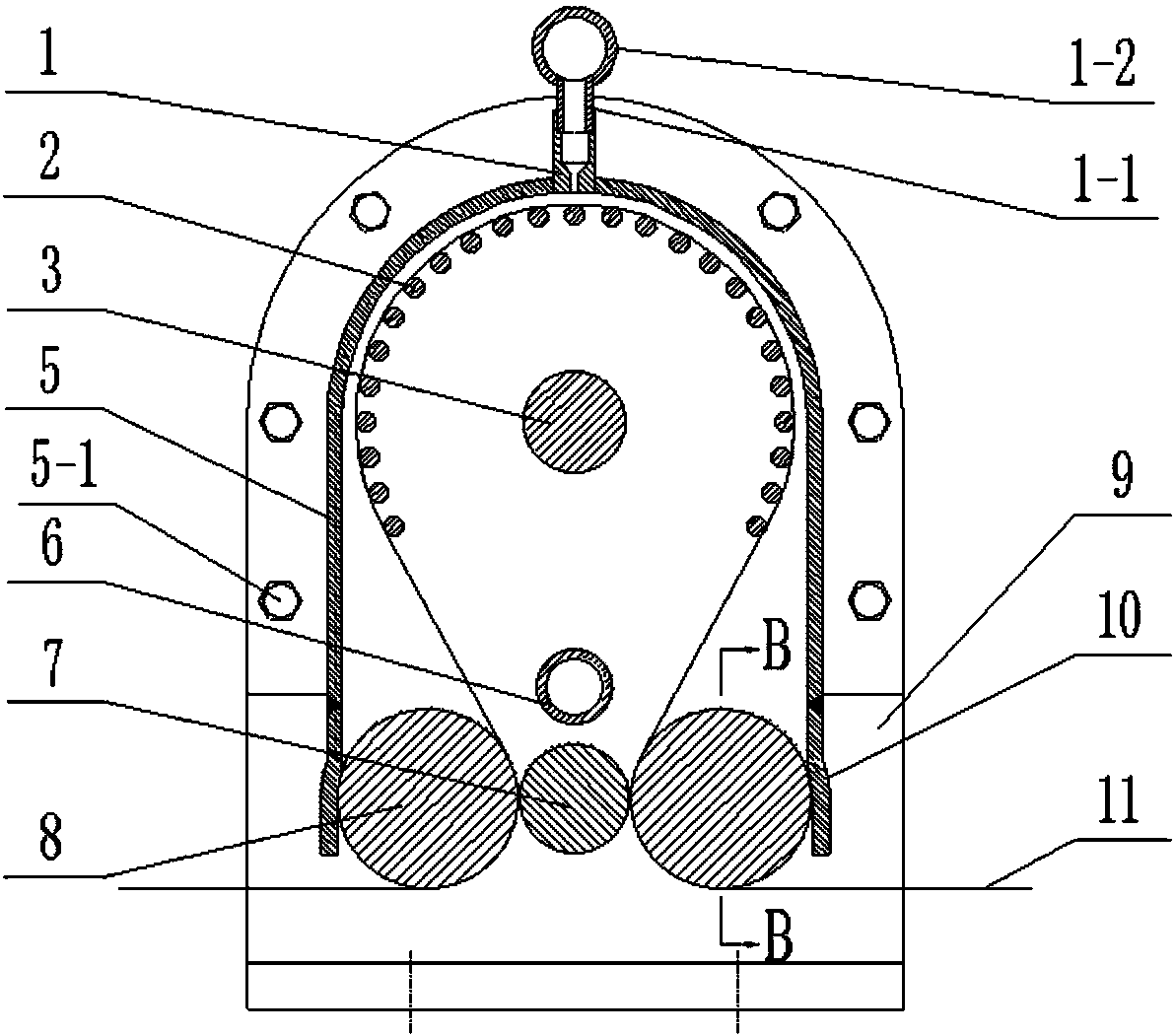
[0028] Embodiment three, the embodiment of supercritical fluid jet dyeing, such as Figure 6 shown.

[0029] Utilize the technological process that the present invention carries out supercritical fluid spray dyeing as:

[0030] Firstly, the supercritical fluid medium in the supercritical fluid medium storage subsystem 12 flows through the supercritical fluid generating subsystem 13 to generate supercritical fluid meeting the conditions of the jet dyeing process.

[0031] Second, the dyed object 11 bypasses the squirrel-cage dyeing cylinder 2 under the guidance of the cloth guide roller 8, runs along the direction of the process requirements with the rotation of the rolling dyeing roller 2, and passes through the cleaning injector 15, dyeing machine, etc. Injector 16 and rinse injector 17 .

[0032] Third, after the pure supercritical fluid in the supercritical fluid generation subsystem 13 flows through the nozzle main pipe 1-2 and the nozzle branch pipe 1-1 of the cleaning ...


PUM

PropertyMeasurementUnit
Outer diameteraaaaaaaaaa
Diameteraaaaaaaaaa
Circle diameteraaaaaaaaaa

Abstract

The invention relates to the field of textile dying equipment, in particular to a novel ejector used for supercritical fluid jet dying. According to the jet dying technological process, the novel ejector is installed in a supercritical fluid jet dying device and is connected with a supercritical fluid generation subsystem, a dye dissolution subsystem and a used fluid recovery and separation subsystem. The novel ejector is composed of a squirrel-cage-type washing and dying cylinder, a transmission supporting rotor, two lateral wall plates, a gear disk or a synchronous wheel, a driving gear or a synchronous belt, a backflow pipe, a flow adjusting cover, a sealing cover, cloth guide rollers, an anti-overflow roller, spray nozzles, spray nozzle branch pipes and spray nozzle header pipes. According to the novel ejector, dying is implemented in the mode that dyed materials are always in dynamic contact with rolling washing and dying rollers which form the squirrel-cage-type washing and dying cylinder, and therefore dying dead zones are not prone to being caused; meanwhile, deformation and tension damage of the dyed materials are effectively eliminated though the supporting effect of the rolling washing and dying rollers, wherein deformation and tension damage are generated under the effects of high-pressure jet flows and traction force; the novel ejector is simple and compact in structure and excellent in manufacturability.

Description

1. Technical field [0001] The invention relates to the field of textile dyeing equipment, in particular to a novel injector for supercritical fluid spraying and dyeing. 2. Background technology [0002] Supercritical fluid dyeing technology fundamentally solves the problem of water pollution in the dyeing industry. At the same time, supercritical fluid dyeing technology has the advantages of supercritical fluid recycling, no pollution discharge, no drying of dyed objects, less fiber damage, simple and quick operation, high dyeing efficiency and low energy consumption, and has a good development and application prospect. At present, most supercritical fluid dyeing devices at home and abroad are dip dyeing devices, which must use high-pressure equipment. At the same time, these devices have high requirements for the tightness of the dyeing device, and also require a good quick-opening or reversing structure, which increases the structure of the device. The complexity and inve...

Claims


Application Information

Patent Timeline
IPC IPC(8): D06B9/02D06B23/20
Inventor 王威强王明禄曲延鹏刘燕王贺
Owner SHANDONG UNIV
Why Eureka
Try Eureka