Oil-water separation method and oil-water separation device

An oil-water separation device and oil-water separation technology, which are applied in separation methods, liquid separation, grease/oily substance/floating matter removal devices, etc., can solve problems such as incompleteness, inability to work after power failure, and difficulty in cleaning, and achieve complete oil-water separation. Energy saving and efficient cleaning

Inactive Publication Date: 2014-09-03
CHONGQING UNIV
View PDF5 Cites 6 Cited by
  • Summary
  • Abstract
  • Description
  • Claims
  • Application Information

AI Technical Summary

Problems solved by technology

[0007] 1. The collection and cleaning of the waste residue in the grease trap is mainly carried out manually with nails and rakes, which is difficult, incomplete, and labor-intensive; there are also submersible pumps with reamers to discharge the waste residue through the pump, but the energy consumption is large and the There are problems such as power failure and inability to work;
[0008] 2. The sludge removal in grease traps (especially buried grease traps) is mainly through water pumps to lift the sludge out of the pool. In addition to some limitations of relying on electricity, it is not easy when to start the pump for sludge and how long it should run. Obtaining accurate judgments can easily lead to unnecessary consumption of motivation;
In particular, the existing oil traps are basically aimed at accumulating large-sized oil in water. How to adapt to the impact of peak flow without energy consumption, and continuously, automatically, and efficiently perform oil floating and dispersing oil in water? Separation and collection of waste oil including emulsified oil and dissolved oil? Relevant public technologies and patents are still very limited

Method used


Image

  • Oil-water separation method and oil-water separation device
  • Oil-water separation method and oil-water separation device
  • Oil-water separation method and oil-water separation device

Examples


Embodiment Construction

[0048] The present invention will be further described in detail below in conjunction with the accompanying drawings.

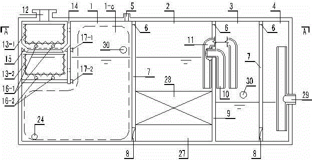
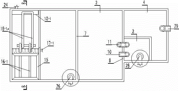
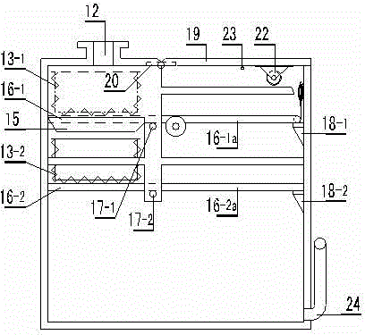
[0049] see figure 1 , figure 2 , image 3 Shown, a kind of oil-water separation method of the present invention is characterized in that comprising the steps:

[0050] 1) Introduce the oily wastewater into the pretreatment unit including two-stage removable grid slag baskets, and remove coarse and larger substances (solids and particles) through the first-stage grid slag baskets, such as diameter or size greater than 5mm Substances, through the secondary mesh slag basket to intercept and remove broken small slag particles, such as substances with a diameter or size less than 5mm;

[0051] 2) For vegetable oil, pass the pretreated oily wastewater through the primary oil-water separation unit at a flow rate of less than 0.0055m / s and a residence time of more than 25min; for animal oil, pass the pretreated oily wastewater at a flow rate of less than 0.0063m...


PUM


Abstract

The invention discloses an oil-water separation method and an oil-water separation device. The device consists of a primary oil-water separation unit, an adsorption and desorption unit, an advanced oil-water separation unit and a drainage unit, wherein a breather pipe is arranged at the top end of the primary oil-water separation unit and communicated with the atmosphere, and a transverse communicating hole is formed in the upper part of a partition between the adjacent units; a coarse grid residue basket in the primary oil-water separation unit is communicated with a fine grid residue basket by virtue of a diversion opening, and both the coarse grid residue basket and the fine grid residue basket are turnover and removable; an oil discharge mechanism consisting of a floating ball accommodating cavity, a floating ball and a plugging cylinder is connected with an oil discharge pipe; an adsorption and desorption packing layer is arranged in the adsorption and desorption unit; the advanced oil-water separation unit is provided with the oil discharge mechanism; the drainage unit is provided with a drainage pipe. The method and the device can be used for continuous, automatic and efficient oil-water separation without manual operation and energy consumption, and can be used for clearing sludge without power equipment, so that the energy is effectively saved; water can be prevented from entering the oil discharge pipe at a peak drainage period, so that the oil-water separation is more thorough.

Description

technical field [0001] The invention belongs to the field of environmental protection water treatment for separating and treating oily sewage, and in particular relates to a high-efficiency, non-powered automatic oil-water separation method and device. [0002] Background technique [0003] Oily wastewater comes from a wide range of sources, such as petroleum refining process, oil tank cleaning in railway locomotive depots, tanker ballasting in shipyards, tank washing, mechanical cutting, car washing, catering, food processing, etc. When the concentration of oil components in the sewage is high, entering the urban sewage treatment plant will increase the operating load, increase oxygen consumption, and reduce the treatment efficiency; entering the natural water body will cause the ingestion, absorption, and enrichment of toxic substances such as benzene rings in the waste water by aquatic organisms At the same time, the surface oil film blocks the oxygen in the air from dis...

Claims


Application Information

Patent Timeline
IPC IPC(8): C02F9/02C02F1/40
Inventor 汪昆平翟俊肖海文何琴张琨江佳玥李雨芬傅驿犇
Owner CHONGQING UNIV
Why Eureka
Try Eureka