
Air separation method capable of being matched with cold energy supply in receiving station

An air separation and matching technology, applied in the direction of cold treatment separation, refrigeration and liquefaction, liquefaction, etc., can solve the problems of insufficient cold energy, full utilization and impact of unstable LNG cold energy, etc., to reduce unit power consumption and obvious social benefits And economic benefits, the effect of high extraction rate

Active Publication Date: 2014-09-03
CHINA NAT OFFSHORE OIL CORP +1
View PDF10 Cites 4 Cited by
  • Summary
  • Abstract
  • Description
  • Claims
  • Application Information

AI Technical Summary

Problems solved by technology

However, the LNG at the receiving station is always gasified during the day, and the available cooling energy is abundant. At night, the LNG gasification is less, and the available cooling energy is insufficient.
This contradiction between the demand and supply of LNG cold energy has seriously affected the application of the above-mentioned air separation method using LNG cold energy, and also seriously affected the full utilization of unstable LNG cold energy.

Method used


Image

  • Air separation method capable of being matched with cold energy supply in receiving station
  • Air separation method capable of being matched with cold energy supply in receiving station

Examples


Embodiment 1

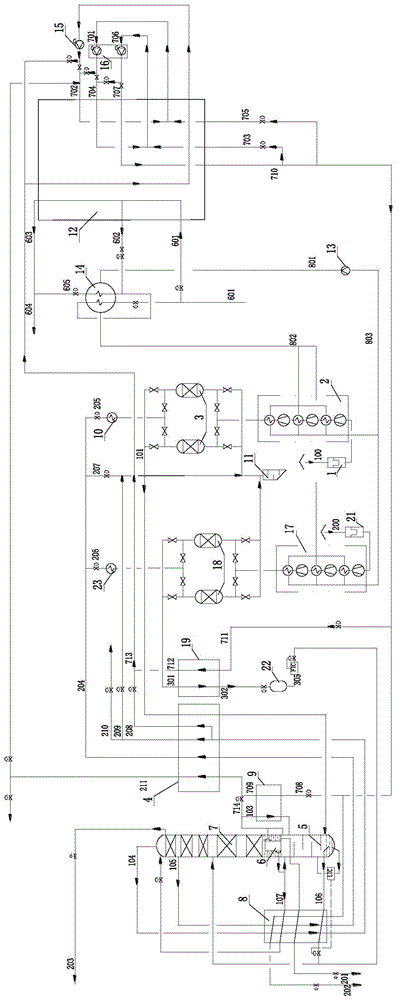
[0017] see figure 1 , an air separation method that can match the cold energy supply of the receiving station, comprising the following steps:

[0018] The first air 100 is inhaled through the air filter 1 and multi-stage compressed by the air compressor 2 (the coolers of each stage are cooled with ethylene glycol aqueous solution) to reach about 0.5 MPa, and then enters the air purifier 3 to remove harmful carbon dioxide, water, acetylene, etc. Impurities, compressed and purified first raw material air 101 is sent to the lower tower 5 of the air separation system.

[0019] The second air 200 is inhaled through the air filter 21 and compressed in multiple stages by the air compressor 17 (the coolers of each stage are cooled with ethylene glycol aqueous solution) to reach about 0.4MPa, and then enters the air purifier 18 to remove impurities such as carbon dioxide, water, and acetylene , the second raw material air 301 after compression and purification is sent to the air liqu...

Embodiment 2

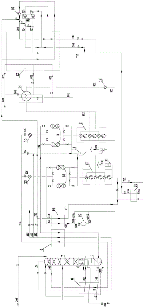
[0038] see figure 2 , an air separation method that can match the cold energy supply of the receiving station. The main difference from Example 1 is that in Example 1, liquid nitrogen is used to provide the required cooling capacity for air separation during the day, and liquid air is used for air separation at night. Air separation provides the required cooling and partly separates the air. And present embodiment then all is to provide required cooling capacity and part separated air for air separation with liquid air no matter daytime and night.

[0039] In the present embodiment, there is no liquid nitrogen-nitrogen heat exchanger 9, so there is no circulating pressure liquid nitrogen 708 and most of the liquid nitrogen product 202 for air separation from the LNG-nitrogen heat exchanger 12, nor is there any Pressure nitrogen 103 and nitrogen 714 drawn from the top.

[0040] In the daytime, one strand is drawn from the high-pressure supercooled liquid nitrogen 710 as the ...


PUM


Abstract

The invention discloses an air separation method capable of being matched with cold energy supply in a receiving station. The method includes the following steps that when LNG supply is sufficient, nitrogen from an air separation system is compressed many times and then exchanges heat with LNG, high-pressure supercooling liquid nitrogen can be obtained, and cooling capacity is provided for the air separation system; a stream of liquid nitrogen is extracted from the high-pressure supercooling liquid nitrogen and throttled and then exchanges heat with second stream of raw material air, the temperature of the liquid nitrogen rises so that low pressure nitrogen can be generated, the low pressure nitrogen is added into the nitrogen exchanging heat with the LNG, the temperature of the second stream of raw material air is lowered so that liquid air can be generated through liquidation, and the liquid air forms stock liquid air; when LNG supply is not sufficient, the stock liquid air is fed into an upper tower of the air separation system, cooling capacity and part of separation air are provided for the air separation system, no heat exchange happens between the LNG and the nitrogen from the air separation system at the moment, the LNG exchanges heat with cooling liquid of a raw material air compressor, and the LNG is fed into a natural gas pipeline after the temperature of the LNG rises to reach the pipeline conveying temperature. With the air separation method, the requirement of the air separation method for LNG cold energy can be well matched with supply of LNG cold energy.

Description

technical field [0001] The invention relates to an air separation method, in particular to an air separation method which utilizes the cold energy of liquefied natural gas, but the cold energy supply of the liquefied natural gas is unstable. Background technique [0002] Chinese invention patent document CN101943512B disclosed an air separation method utilizing the cold energy of liquefied natural gas on January 12, 2011. This air separation method requires continuous, uninterrupted and stable supply of cold energy of liquefied natural gas. However, the LNG at the receiving station is always gasified during the day, and the available cooling energy is abundant, and at night, the LNG is less gasified, and the available cooling energy is insufficient. This contradiction between the demand and supply of LNG cold energy has seriously affected the application of the above-mentioned air separation method utilizing LNG cold energy, and also seriously affected the full utilization o...

Claims


Application Information

Patent Timeline
Patent Type & Authority Applications(China)
IPC IPC(8): F25J3/04
CPCF25J3/0406F25J3/04018F25J3/04157F25J3/04169F25J3/04224F25J3/0423F25J3/04272F25J3/04351F25J3/04412F25J3/04478F25J2205/62F25J2210/62F25J2230/04F25J2250/20F25J2270/02F25J2270/904
Inventor 江克忠夏永强江蓉张磊赖勇杰王玉川魏林瑞胡钰
Owner CHINA NAT OFFSHORE OIL CORP
Learn More