Automatic batching system

An automatic batching and batching machine technology, applied in the directions of dissolution, chemical instruments and methods, mixing methods, etc., can solve the problems of low batching accuracy, high labor intensity, and chaotic on-site environment, so as to improve batching accuracy, reduce labor intensity, improve The effect of the work environment

Active Publication Date: 2014-09-10
桐乡市京工树脂有限公司
View PDF3 Cites 19 Cited by
  • Summary
  • Abstract
  • Description
  • Claims
  • Application Information

AI Technical Summary

Problems solved by technology

[0003] The purpose of the present invention is to overcome the deficiencies of the prior art and provide an automatic batching system for denitrification catalyst raw materials to solve the problem that in the existing denitrification catalyst production technology, the batching process basically uses manual batching, which has high labor intensity and batching accuracy. Low, on-site environment chaos and other issues

Method used


Image

  • Automatic batching system

Examples


Embodiment 1

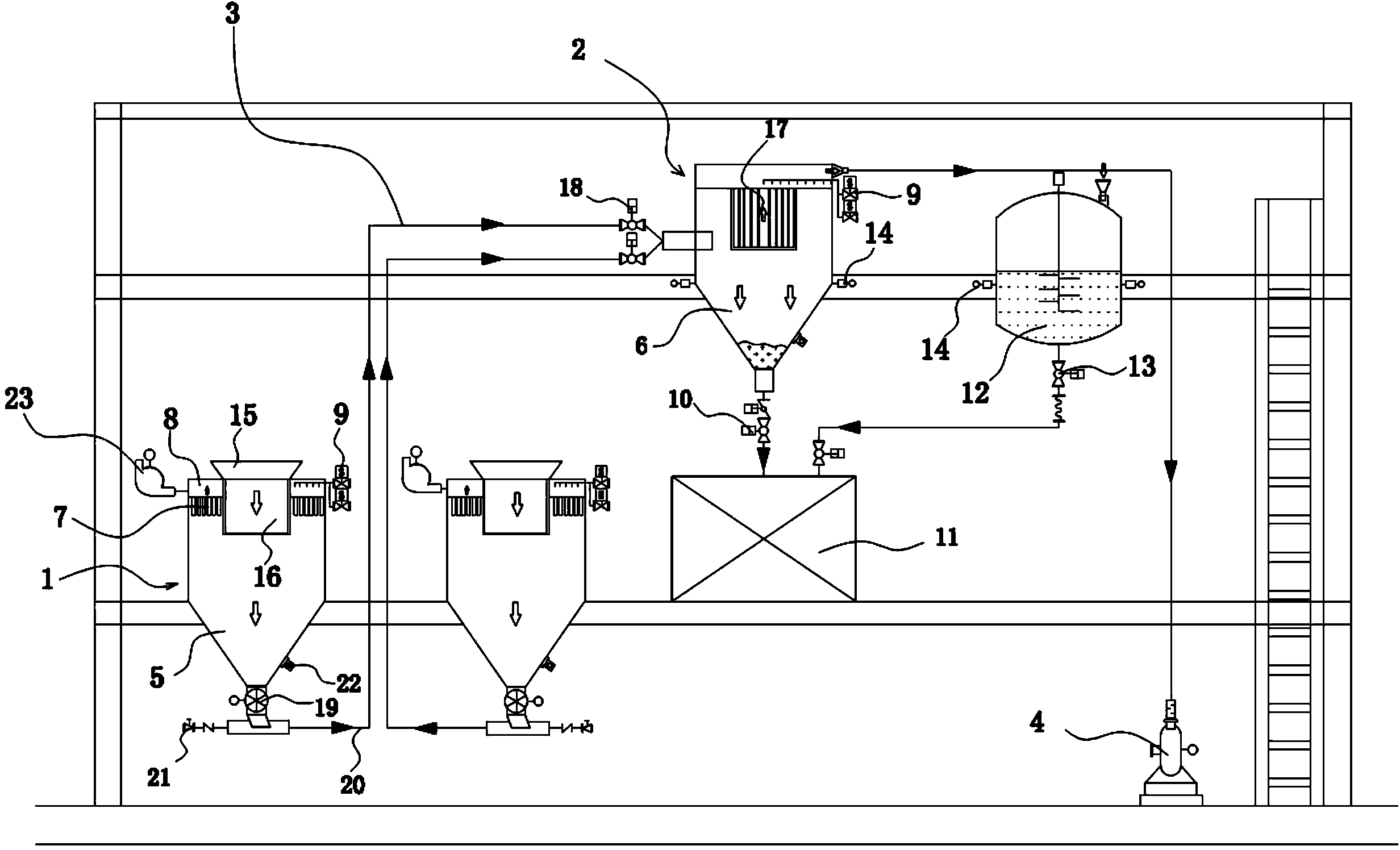
[0022] Such as figure 1 As shown, the automatic batching system includes a control device, a solid material delivery system and a liquid material delivery system;

[0023] The solid raw material conveying system includes a batching machine 1, a feeding machine 2 and a vacuum conveying device; the vacuum conveying device includes a vacuum conveying pipe 3 and a vacuum pump 4; The outlet of the feeder bin 5 is connected to the feeder inlet of the feeding machine through a vacuum conveying pipe. The feeding bin 6 of the feeding machine is an airtight cavity, and the upper part of the bin is separated by a dust filter 7 to form a pumping chamber. Vacuum channel 8, the vacuum channel communicates with the vacuum pump 4 through the vacuum conveying pipe; the discharge port of the feeding machine silo is provided with a pneumatic butterfly valve 10, and is connected with the feed port of the mixer 11 through the pneumatic butterfly valve 10;

[0024] The liquid raw material conveyin...

Embodiment 2

[0033] Work process and steps of the present invention are as follows:

[0034] First, put raw materials such as titanium tungsten powder and titanium tungsten silicon powder packaging bags into the corresponding powder batching machine discharge port, the raw materials fall into the hopper by gravity, and open one of the powder batching machines after the raw materials fall into the hopper The rotary feeder, and then turn on the vacuum pump (Roots vacuum pump), the rotary feeder at the bottom of the batching machine is connected to the vacuum conveying pipeline, and the raw material is pumped to the position of the powder feeder by vacuum negative pressure, and the raw material is waited for After reaching the desired weight for production, turn off the Roots vacuum pump. By analogy, turn on the rotary feeder of another powder batching machine to complete the weighing of raw materials.

[0035] The dust generated in the silo during the raw material unloading process is absor...


PUM


Abstract

An automatic batching system comprises a solid material conveying system and a liquid material conveying system; the solid material conveying system comprises a batching machine, a feeding machine and a vacuum conveying device; the vacuum conveying device comprises a vacuum conveying pipe and a vacuum extractor, a bin discharging hole of the batching machine is connected with a bin feeding hole of the feeding machine through a vacuum conveying pipe, a bin of the feeding machine is a closed cavity, the upper portion of the bin is spaced through a dedusting filter to form a vacuumized channel, and the vacuumized channel is communicated with the vacuum extractor through the vacuum conveying pipe; a bin discharging hole of the feeding machine is connected with a mixer feeding hole through a pneumatic butterfly valve; the liquid material conveying system comprises a liquid stirring kettle; a discharging hole of the stirring kettle is provided with an automatic ball valve and is connected with the mixer feeding hole through the automatic ball valve; the powder feeding machine and the stirring kettle are respectively provided with a weighing sensor. The full-automatic batching system is adopted, the automatic whole batching process and continuous batching are achieved, and the batching precision of raw materials is improved.

Description

technical field [0001] The invention relates to an automatic batching system for raw materials, in particular to an automatic batching system for denitrification catalyst raw materials. Background technique [0002] Nitrogen oxides (NO X , including NO, NO 2 and other compounds) is one of the main pollutants causing air pollution. As the country pays more and more attention to environmental protection, especially air pollutants, more thermal power plants will carry out flue gas denitration treatment in the future. Selective catalytic reduction denitrification (SCR) is currently the most widely used, most efficient, and most mature denitrification technology, and its focus is on denitrification catalysts. The main principle of SCR refers to the use of a reducing agent (anhydrous ammonia, ammonia water or urea) to "selectively" interact with NO in the flue gas under the action of a catalyst. X The reaction produces harmless nitrogen and water, thereby removing NO from the ...

Claims


Application Information

Patent Timeline
Patent Type & Authority Applications(China)
IPC IPC(8): B01F3/12
Inventor 周珮萱王利亚
Owner 桐乡市京工树脂有限公司
Why Eureka
Try Eureka