Temperature control circuit of hemisphere resonance gyro combination

A hemispherical resonant gyroscope and temperature control circuit technology, applied in the field of satellite attitude control, can solve the problems affecting time delay, gyro drift, invariable temperature control points, etc., and achieve the effect of improving use accuracy and reducing output noise and drift.

Inactive Publication Date: 2014-09-10
SHANGHAI XINYUE METER FACTORY
View PDF6 Cites 9 Cited by
  • Summary
  • Abstract
  • Description
  • Claims
  • Application Information

AI Technical Summary

Problems solved by technology

The change of the working temperature of the hemispherical gyro resonator will cause the drift of the gyro, which is mainly manifested in the inconsistency of the zero bias instability started at different temperatures, the output has a more obvious trend item, and the temperature affects the delay under continuous working conditions
[0005] The existing gyro combinations usually have the following deficiencies. One is the use of the traditional Cartesian coordinate system support structure, resulting in a large difference in the temperature gradient of each gyroscope, which is not conducive to the temperature control of the combination.
Therefore, relevant scientific and technical personnel are working to improve the support structure; second, the existing temperature information collection is to convert the temperature change into a voltage signal through a Huygens bridge, and then convert it into a digital signal through an analog-to-digital converter. The converter cannot achieve high efficiency, so the anti-interference ability is poor
The third is that the temperature control point of the existing temperature control is not variable in the entire use environment, which will cause a large power consumption of the temperature control in a low temperature environment, and cause a serious burden on the system power supply

Method used


Image

  • Temperature control circuit of hemisphere resonance gyro combination
  • Temperature control circuit of hemisphere resonance gyro combination

Examples


Embodiment Construction

[0018] The present invention will be further described below in conjunction with the accompanying drawings and embodiments.

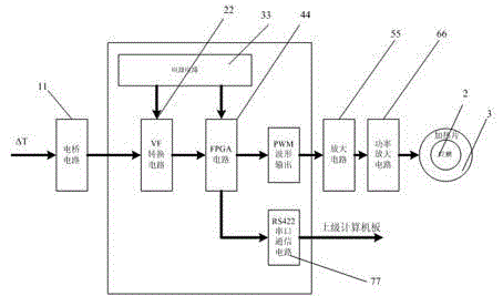
[0019] Such as figure 1 As shown, it is a block diagram of the temperature control circuit of the hemispherical resonant gyro combination of the present invention, including a temperature control acquisition unit, a control unit, and a drive unit. One end of the control unit is connected with the temperature control acquisition unit, and the other end is connected with the drive unit. The heating pad 2 on the gyro is connected. The temperature change is converted into a voltage conversion, and then the voltage change is converted into a pulse number change. The pulse number is output through a software proportional integral differential algorithm to output a pulse width modulation waveform to drive the power FET on the temperature control drive board, and then control the heater 2. On-off time to control the average current. The temperature change of ...


PUM


Abstract

The invention discloses a temperature control circuit of a hemisphere resonance gyro combination. The temperature control circuit comprises a temperature control acquisition unit, a control unit and a driving unit. One end of the control unit is connected with the temperature control acquisition unit, the other end of the control unit communicates with the driving unit, and the driving unit is connected with a heating sheet attached to a gyro. According to the invention, a digitalization mode of converting temperature to the number of pulses is employed, proportional integration differential (PID) control algorithm processing is performed on acquired information in a field programmable gate array (FPGA), and then pulse width modulation (PWM) waveforms are output for controlling the output currents of the heating sheet. The temperature change of the gyro combination is controlled within a precision scope, a stable temperature environment is provided for the gyro combination, the gyro output noise and drifting are reduced, and the application precision of the gyro is improved.

Description

[0001] technical field [0002] The invention relates to a satellite attitude control technology, in particular to a temperature control circuit for a hemispherical resonant gyro combination of a satellite. [0003] Background technique [0004] The hemispherical resonant gyro combination is an important sensitive device of the satellite attitude and orbit control subsystem. It is used to sense the inertial angular velocity of the satellite star, output its component on the star coordinate system, and provide continuous three-axis inertial angular velocity for each working mode and flight stage of the satellite. information. The change of the operating temperature of the hemispherical gyro resonator will cause the drift of the gyro, which is mainly manifested in the inconsistency of the bias instability at startup at different temperatures, the output has a more obvious trend item, and the temperature affects the delay under continuous working conditions. [0005] The exis...

Claims


Application Information

Patent Timeline
Patent Type & Authority Applications(China)
IPC IPC(8): G05D23/24
Inventor 蔡雄荣义杰齐轶楠张强赵万良孙兰
Owner SHANGHAI XINYUE METER FACTORY
Why Eureka
Try Eureka